Theory and Use of Curved Surface Correction (CSC) Software in Olympus NDT EPOCH Series Flaw Detectors
Contemporary digital ultrasonic flaw detectors calculate commonly used parameters for reflector position in angle beam testing, typically including sound path length, flaw depth, surface distance, and beam leg. These calculations are based on a measured pulse transit time, calibrated material sound velocity and probe zero offset, and entered values for test piece thickness, beam angle, and beam index point. By default, calculations assume a flat test piece. In the case of circumferential inspection of tubular parts, the calculations must be adjusted for the effects of test piece curvature. This is done by means of a mathematical correction based on entered outside and inside diameters of the test piece. The following topics will be reviewed.
- Mathematical Theory
- Previous Approaches
- Implementation of Curved Surface Correction in EPOCH series flaw detectors
- Measurement examples
- Use of contoured wedges
1. Mathematical theory
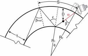
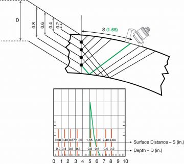
In the case of common flat plate tests and axially-oriented tests of pipes and similar products, leg length and reflector depth and surface distance can be calculated through simple trigonometry through the formulas below. But when testing a curved part in the circumferential direction, these formulas become inaccurate due to the curvature that effectively causes reflectors to drop away from the probe, which lengthens the sound path and changes the reflection angle at the inside surface of the part. For example, compare similar conditions for a 45° beam in flat and curved plates both 20 mm thick. The signal obtained at a 35mm sound path length in a flat plate corresponds to a reflector located at a depth of 15.2mm, 24.8mm from the exit point. But the same 35 mm sound path in a 100mm diameter pipe corresponds to a reflector 19.2 mm deep from the OD surface and 31.7mm along the test surface from the exit point to the point over the reflector.
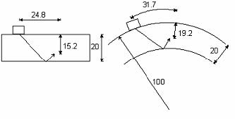
To correct for curvature, a number of mathematical relationships can be applied, based on the angles, measured sound path and dimensions defined below. Utilizing these formulas with leg management enables proper calculation of surface projection and vertical depth of flaws.
| Legend for equations: S = Surface Distance Β = Angle of Refraction Α = Sound path distance t = Thickness R1 = Inside Radius R2 = Outside Radius Βmax = Maximum angle of refraction Ε = Angle of reflection at ID Φ = Projection angle D = Depth of reflector |
1. Projection angle at ID (first leg)
Φ = sin-1(R2/R1 sinΒ)
2. Sound path distance Α, half skip
Α = R1∗sin(Φ_Β)/sin(Β)
3. Depth of reflector D
D = R2 – √Α2 + R22 - 2R2ΑcosΒ
4. Surface distance S
S = ΠR2/180[sin-1(R2/R1 sinΒ)-Β] Note: for first leg test, R1 = t-D
5. Maximum angle of refraction for a given wall thickness (angle of impingement)
Βmax = sin-1(R1/R2)
2. Previous approaches
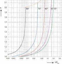
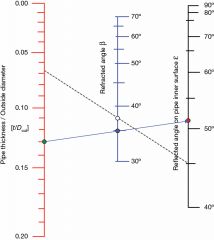
Traditional analog flaw detectors measured sound path length only and could not automatically calculate reflector depth or surface distance, or count skip legs. Live automatic displays of these additional dimensional parameters, based on trigonometric calculations, were introduced with the development of digital instruments. However early model digital flaw detectors calculated depth for flat test pieces only. Both with these instruments and analog flaw detectors, operators performing circumferential testing on pipes and similar curved test pieces used graphs and nomograms such as the ones below to calculate dimensions.
The graph at left is used to determine a correction factor k that is based on refracted angle and the ratio of wall thickness and outside diameter. The nomogram at right is used to determine the actual reflected angle at the inside of the curved surface, which because of the curvature is less than the refracted beam angle at the sound entry point.
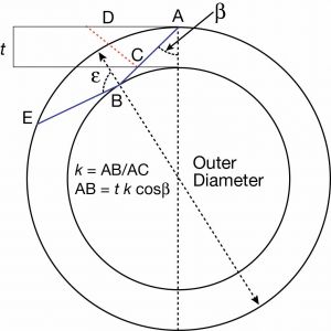
Once k and the refracted angle Β have been determined, it is possible to calculate the actual leg length AB from the formula:
AB = tk cosΒ
Once the leg length is known, a reflector can be accurately placed within the first or second leg of the sound path based on the measured sound path length. Further calculations of flaw depth and surface position must be done manually. As an alternative to calculations, look-up tables have been published that relate these geometrical corrections to test piece diameter, wall thickness, and inspection angles.
In the absence of software for curved surface correction, another alternative to manual calculations or look-up tables was to empirically set up flaw detectors with the aid of a reference standard representing the tube wall in question and incorporating a series of side drilled holes. Reflections from the multiple reference holes can be identified with respect to horizontal position and a screen overlay can be used to mark their vertical depth and surface projected positions on the display. The resulting screen display is horizontally non-linear, but reflector positions can be extrapolated from it by referencing the overlay.
3. Implementation of Curved Surface Correction in EPOCH series flaw detectors
The Curved Surface Correction (CSC) software in the EPOCH series flaw detectors performs calculations automatically based on setup information input by the user.
These calculations assume that initial probe calibration for sound velocity and zero offset have been performed as usual on an IIW-type block or similar flat reference block. Following that calibration, the operator enters the probe angle, the thickness of the test piece, the “X value” (the distance between the beam index point and front edge of the wedge), and the part diameter. The EPOCH software then uses that information plus the measured sound path length to calculate and display the following, based on the equations in Section 1.
| sound path length | |
| Projected surface distance from front of probe (or beam index point if no X-value is input) along outside of the test piece | |
| depth of reflector |
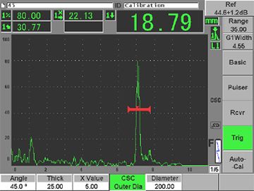
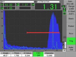
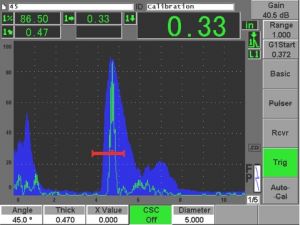
Assuming proper calibration and setup, these measurements will be as accurate as those on a flat test piece in a given setup. The example screens below show a typical measurement of a first leg reflector in a thick wall reference sample, shown with and without CSC correction. When the correction is applied, the flaw depth measurement is shallower (1.13” versus 1.31”) and the surface distance or projection is farther from the probe (1.39” versus 1.07”).
Additional notes:
- In all tests that involve circumferential probe alignment it is very important to hold the probe normal to the surface rather than tilting it. Tilting will skew the sound beam and effectively change the refracted angle in the test piece.
- In cases where the ratio of wall thickness to diameter is large, the sound beam at a given angle may not reflect off the ID, instead continuing straight across to the OD without a skip. (See section 1, equation 6.) In these cases CSC calculations are not valid and the EPOCH will not report dimensional information.
4. Example measurements using EPOCH 600
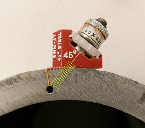
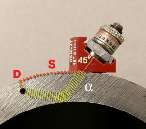
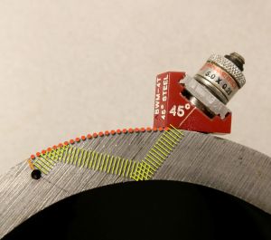
First leg measurements of pipe section with 0.1” side drilled holes as shown in photograph, using EPOCH 600 flaw detector and A543S-RM transducer with ABWM-4T-45 wedge. Diameter is 5.0”, wall thickness 0.470”. Reflectors are 0.1” diameter side drilled holes with centerline depths of 0.160” and 0.310” from OD (1/3 and 2/3 thickness).
The SDH diameter factor causes a small offset in the reading. When establishing the physical location of the reflector within the part it is important to measure depth and surface projection to the normal of the outer radius tangent. The measured sound path displayed is not affected by CSC correction status. Proper calibration of zero offset and material velocity are required. In the examples below:
- Physical measurement of sound path to hole OD
- Surface projection is measured from the beam index point (X Value=0)
First leg measurements
| FIRST LEG | CSC Off | CSC ON | Physical Measurement |
| Sound Path | 0.47 | 0.47 | 0.46 |
| Depth | 0.33 | 0.31 | 0.31 |
| Surface distance | 0.33 | 0.38 | 0.40 |
Second leg measurements
| SECOND LEG | CSC Off | CSC ON | Physical Measurement |
| Sound Path | 1.14 | 1.14 | NA |
| Depth | 0.14 | 0.27 | 0.22 |
| Surface distance | 0.8 | 1.04 | 1.03 |
Third leg measurements of pipe section with 0.1” side drilled holes.
| THIRD LEG | CSC Off | CSC ON | Physical Measurement |
| Sound Path | 1.78 | 1.78 | NA |
| Depth | 0.32 | 0.16 | 0.160 |
| Surface distance | 1.26 | 1.54 | 1.50 |
5. Use of contoured wedges
As the diameter of a cylindrical test piece become smaller, circumferentially oriented coupling of conventional wedges becomes progressively more challenging, due to reduced contact area and the increased possibility of rocking. For that reason, special cylindrically contoured wedges are sometimes used on smaller diameter test pieces. As a guideline, the International Institute of Welding recommends contouring whenever test piece radius R is less than the length of the wedge W squared divided by four:
The SDH diameter factor causes a small offset in the reading. When establishing the physical location of the reflector within the part it is important to measure depth and surface projection to the normal of the outer radius tangent. The measured sound path displayed is not affected by CSC correction status. Proper calibration of zero offset and material velocity are required. In the examples below:
R W2 / 4
ASTM standard E-164, Standard Practice for Ultrasonic Contact Examination of Weldments, calls for use of radiused wedges whenever the part diameter is less than 20 inches or 500 mm. Olympus NDT experience suggests that this is a conservative recommendation, especially when using small angle beam assemblies, but it is up to the user to determine applicability to specific test.
The minimum outside diameter for which a wedge of a given size can be cylindrically contoured depends on mechanical considerations related to wedge size and angle. The following chart lists the approximate minimum contouring diameter for three common Panametrics-NDT wedge types.
| Minimum OD for cyl. contour | 45 degree | 60 degree | 70 degree |
| ABWM-4T | 0.8” or 20 mm | 1.1” or 28 mm/td> | 1.5” or 38 mm |
| ABWM-5T | 1.5” or 38 mm | 2.2” or 56 mm | 2.8” or 70 mm |
| ABWM-6T | 1.2” or 30 mm | 1.7” or 43 mm | 2.4” or 60 mm |
Panametrics-NDT contoured wedges maintain a beam index point at the BIP location marked on the wedge, and the nominal wedge angle is calculated based on beam refraction at that point. However it is important to note that cylindrical wedge contouring affects the incident angle and thus the refracted angle from front to back across the diameter of the beam, resulting in a range of refracted angles and effectively a defocusing and broadening of the beam in that axis.
When using contoured wedges, appropriately contoured reference blocks must also be used to calibrate zero offset and verify beam index point and refracted angle. Conventional IIW and AWS-type reference blocks cannot be used because of the gap between the block and the concave surface of the wedge.
