Application
Evaluating the integrity of spot weld joints in metal.
Background
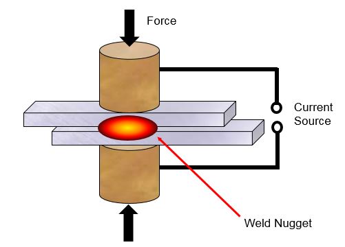
Spot welding is a common technique for joining two pieces of metal, usually thin sheets or plates, by means of a series of small circular tack joints. The process is widely used in the automotive industry for body assembly and some chassis joints, and by other types of sheet metal fabricators as well. Spot welds are made by pressing electrodes against both sides of the parts to be joined and passing a high current through them, which momentarily creates a pool of molten metal that solidifies into a round joint known as a nugget.
If the weld is improperly formed, it is possible that the two parts may not fuse completely, or that the area of the nugget may be smaller than what is required for a strong joint. These problems are seldom visible to optical inspection, and destructive pull tests are inefficient and limited to a few samples. However, with proper equipment and technique, ultrasonic spot weld inspection can quickly and nondestructively provide valuable information about weld quality.
Equipment
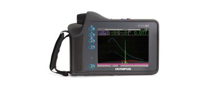
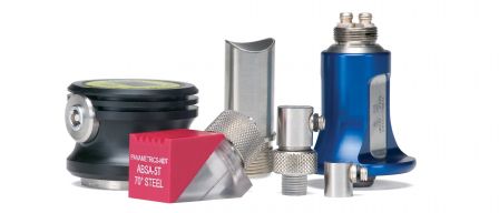
The recommended instruments for spot weld inspection are the EPOCH 650 or EPOCH 1000 ultrasonic flaw detector. Spot weld testing requires coupling sound into a cup-shaped weld, typically 3 to 6 mm (0.125 to 0.250 in.) in diameter and generating multiple back wall echoes at high frequency. Olympus offers a wide variety of delay lines and captive water column transducers with a frequency range from 10 to 20 MHz for this purpose. Delay line transducers use a small plastic waveguide to couple sound energy from the transducer element to the test piece. Captive water column transducers incorporate a pliable rubber membrane enclosing a column of water that conforms to the topography of the spot weld to optimize coupling. In the case of delay line transducers, the delay line diameter and element diameter are normally matched to the nominal nugget diameter to within a few tenths of a millimeter. In the case of captive water column transducers, the element diameter is normally matched to the nominal nugget diameter. For further details on transducer selection, contact Olympus. |  |
Theory of Operation
In a good weld, the spacing between echoes will be proportional to the thickness of the weld, and the decay rate (the rate at which successive echoes decrease in amplitude) will be related to the attenuation within the nugget. There will be a characteristic echo pattern associated with each weld condition; good, un-weld, undersized weld, and stick weld. It is encouraged to utilize the template storage software option which stores and recalls the outlines of the various echo patterns of each weld condition. Each echo pattern can be easily overlaid onto the live A-scan with a push of a button to facilitate comparison and enhance inspection. Multiple templates can be stored and an -A- denotes the active template selection. | 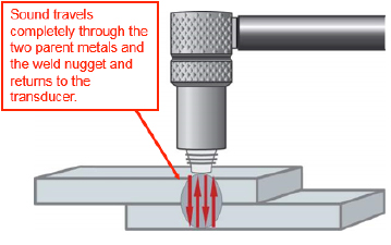  |
If there is no fusion between the two pieces of metal (a "no weld" or "un-weld" condition), then the successive echoes will be much closer together and larger in amplitude. | 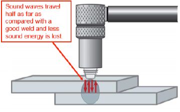 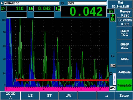 |
In the case of an undersized weld, only a portion of the sound beam will reflect from the total thickness of the two metal sheets, while a portion reflects from a single thickness. This creates a pattern in which small peaks representing single-sheet thickness appear between the larger and more widely separated peaks representing the full weld thickness. | 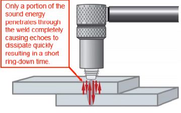 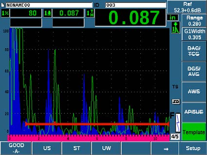 |
Finally, in a stick weld (or stuck weld) condition where the metal sheets are fused but because of insufficient heating the weld nugget is not fully formed, the echo decay rate will change, resulting in larger peaks appearing on screen with a longer ring-down time. This is because the grain scattering effect of a fully formed nugget is absent and the weld zone is more transmissive than in the case of a fully formed weld. | 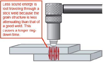 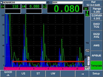 |
