Informationen zur Auswahl von Wirbelstromsonden
The selection of the right eddy current probe is of great importance in the success of your inspection. In these pages, we have included useful information to help you make the right choice.
Absolute Probes (Single-Coil Probes)
The earliest form of eddy current instruments operated with a single-coil probe that was wound to a specific value frequency. Many newer models of eddy current instruments have kept this circuitry as a popular option for users while also incorporating more sophisticated functions. When these probes are used, a balance coil is also required which may be set from within the eddy current instrument or is commonly found within the probe housing, the cable connector or in a separate adapter (see Fig. 1).
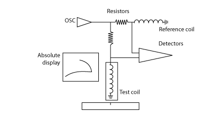
Figure 1
A problem can arise when the probe inductance value is not close enough to the value of the balance coil causing the instrument not to balance correctly. The result is poor performance (noisy or insensitive) or no response at all (signal saturation).
Bridge Type Probes
In this configuration the probe coils are located in an electrical "bridge" (see fig. 2). The instrument balances the bridge and any change in balance is displayed as a signal. In this arrangement, the same coil produces the eddy currents and detects the impedance changes caused by the defects (or any other variables). Almost all instruments are able to operate with this type of coil arrangement.
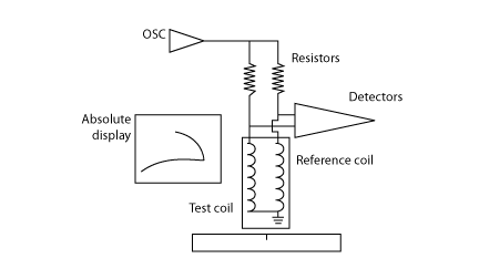
Figure 2
Reflection Type Probe
These probes are also known as send-receive or driver-pickup. In this configuration, the eddy currents are produced by a coil connected to the instrument's oscillator (driver). The signals received back in the probe are detected by separate coils called pickups (see Fig. 3 and Fig. 4). All new impedance plane instruments and also many older models are able to operate in both bridge and reflection modes. If you are in doubt, call the manufacturer or give us a call.
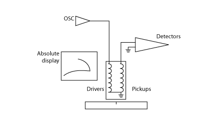
Figure 3
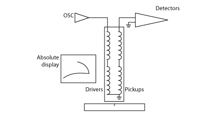
Figure 4
Bridge or Reflection?
This is a common question asked by those involved in trying to select the best probe for an inspection. The answer is "It depends." Let us consider both systems.
Gain: Reflection probes will give a higher gain, particularly if they are "tuned" to a specific frequency, but normally the difference is on average about 6 dB. It is true that this doubles the signal, but if you consider that the instruments are able to give this increase of gain easily, it is not so important. Nevertheless, in critical applications this increase is very welcomed.
Frequency range: Reflection probes do not need to balance the driver to the pickup coils. This means that they will give a wider frequency range. As long as the driver produces eddy currents, the pickup will detect them and some signal will be displayed. This may not provide good information at certain frequencies, but the probe is still working!
Bridge type probes used to give a limited frequency span in the older instruments, as these had to balance an electrical bridge using its other arms (X and R controls). In modern instruments, the bridge is normally formed with fixed precision resistors, or a fixed transformer inside it. The signals detected in this manner are electronically processed without any "mechanical" adjustments, and this means a greater ability to balance over a wider frequency range.
Drift: Probe drift is mostly caused by temperature change in the coils. This may be caused by varying
ambient temperature, or the heat produced by the oscillator current, or both. There are design parameters that can be optimized to reduce drift, such as wire diameter and ferrite selection, but reflection probes are normally a good choice to avoid this problem even more.
In a reflection probe, the driver current does not flow through the pickup coils; in fact, the magnetic field received back from the specimen is normally much smaller and, consequently, the current flowing in the pickups is also reduced. Most probe types (pencil, spot, ring, bolt hole, etc.) can be made as bridge or reflection. Keep in mind that a reflection probe is almost invariably more difficult to manufacture and therefore more expensive.
Absolute, Bridge and Differential Probes
This is an area where some confusion exists. Many users have called a probe "differential" when the signal displayed gives an up and down movement or a figure 8 type signal. This is caused by the two coils sensing the defect in sequence. When both sensing coils are on the probe surface, they compensate for lift-off and as a result no line is visible (see Fig. 5).
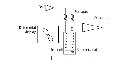
Figure 5
In contrast, an absolute or bridge display is produced by a single sensing coil (see Fig. 1 through Fig. 4), giving a single, upward movement with a near horizontal lift-off line. Others have called a probe "differential" simply when the coils were connected differentially such as in a bridge circuit. The problem with this definition is that probes can be connected differentially in a reflection system as well as when using two pickups (such as most scanner-driven bolt hole probes). In this case, the two pickup coils are positioned close to one another and contained within a driver coil (see Fig. 6).

Figure 6
The best way out of this confusion is often to specify the probe as absolute, bridge, reflection, bridge differential or reflection differential as needed. It makes more sense to qualify the description according to the displayed signal, since this is what really matters and not many people are concerned as to how the coils are connected internally.
Shielded and Unshielded Probes
Probes are normally available in both shielded and unshielded versions; however, there is an increasing
demand for the shielded variety. Shielding restricts the magnetic field produced by the coils to the physical size of the probe. A shield can be made of various materials, but the most common are: ferrite (like a ceramic made of iron oxides), Mumetal, and mild steel. Ferrite make the best shielding because they provide an easy path for the magnetic field but has poor conductivity. This means that there is little eddy current loss in the shield itself. Mild steel has more losses but is widely used for spot probes and ring probes due to its ease of machining when ferrite is not available in certain sizes or shapes. Mumetal is sometimes for pencil probes as it is available in thin sheet; however, it is less effective than ferrite.
Shielding has several advantages: first, it allows the probe to be used near geometry changes, such as edges, without giving false indications; next, it allows the probe to touch ferrous fastener heads with minimal interference; last, it allows the detection of smaller defects due to the stronger magnetic field concentrated in a smaller area.
On the other hand, unshielded probes allow somewhat deeper penetration due to the larger magnetic field. They are also slightly more tolerant to lift-off. Unshielded probes are recommended for the inspection of ferrous materials (steel) for surface cracks, and in particular with meter instruments. The reason for this is that the meter response is too slow to allow the signal from a shielded probe to be displayed at normal scanning speeds due to the smaller sensitive area.
Adapters
To connect a probe with a connector different from the type used on the instrument, it is necessary to use an adapter. An adapter consists of two different connectors joined and wired to match the inputs and outputs as necessary. It is normally housed in a short body that can be positioned at the instrument's input. Sometimes, it is also possible to have a "cable adapter," which is made to match a connector located at the probe body. Depending on the instrument's wiring, it may be possible to have a single adapter for both bridge and reflection probes. In other cases, it is necessary to have two separate adapters or use a switchable type.