Eddy Current Probes and Application Guide

Introduction
This paper is intended to provide information to help the user in selecting the right E.C. probe(s) for a given inspection. Using this data, best results will be achieved by optimizing the frequency and choosing a suitable instrument.
The subject is divided into three sections -
1. Coil types available
2. Typical applications
3. New developents
1. COIL TYPES AVAILABLE
The early E.C. coils generally had either no core ( air core) or a ferrite center core only. Meter instruments were used almost exclusively and sensitivity was comparatively low, but in most cases adequate. Many inspections are still being done using this type of comparatively large, low sensitivity coils.
Absolute Type Coils
A very widely used type coil is a 100 kHz with a diameter of .1 in. (2.5 mm) to .2 in. (5 mm) that fits most bridge type older meter instruments (Figure 1). The sensitivity is acceptable for long cracks that exceed the probe diameter by a factor of approximately 2, as the field is considerably larger than the coil size. This also produces a large edge effect.

Figure 1
A suitable alternative now offered is a smaller coil approximately .060 in. (1.5 mm) diameter with a shield (preferably ferrite) around it. This gives improved sensitivity particularly to short cracks and good isolation from edges, bolt heads, etc. 1
The older probes were normally calibrated using an infinitely long (to the coil) notch, .040 in. (1 mm)or ,020 in. (.5 mm), and their sensitivity will drop off rapidly with shorter notches. The new probes maintain their sensitivity with a notch approximately the internal diameter of the ferrite shield and will still detect a shorter one.
Even meter instruments benefit from this type of coil, but probing speed is limited as the needle needs time to respond. Display-type instruments allow for much faster scanning. Larger surface type probes respond in a similar way to the above. Shielding produces similar improvements when looking for subsurface cracks or corrosion.
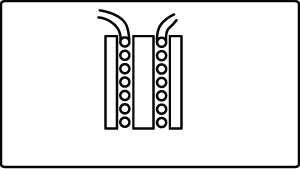
Figure 2
Differential Type Coils
Differential coils have the attraction of built-in lift-off compensation. This has made them useful for many applications.
The older types of coils had no ferrite shield and they were built just by placing two coils side-by-side (Figure 3). Later types added individual shields (Figure 4), but the greatest improvement to the sensitivity was achieved when both coils were placed within a common shield (Figure 5). Differential type probes are mostly used in small sizes for surface crack detection only.
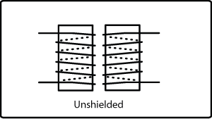
Figure 3
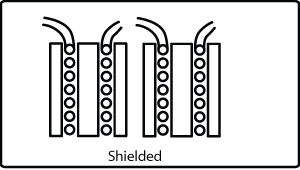
Figure 4

Figure 5
In a probe of this type both coils are wound in opposition. Consequently, signals that affect both simultaneously will cancel out (such as lift- off). Normally the air point and the working point will be close, but some difference is present due to small coil variations.
Normal scan direction is as shown (Figure 6), giving the typical display presentation. The double indication is, in fact helpful, as it doubles the size of the defect in the screen (Figure 7).
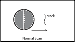
Figure 6
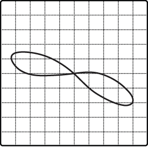
Figure 7
Sometimes it is necessary to scan in the same direction as the cracks (Figure 8). This is permissible and the result will be similar for a very short defect. A larger defect affecting both coils will tend to cancel out because they are in opposition, but in practice there are enough differences in angle and depth for this not to happen totally. In any case, the ends of the crack will show normally.
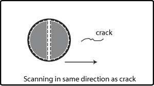
FIgure 8
The probe body has a line to show the normal scan direction. These coils can be fitted in pencil, bore hole or molded probes to fit almost any shape.
Bridge and Reflection Coils
Older coils were normally connected to the two branches of a bridge configuration (Figure 9). Later coils have also been used in the reflection mode where separate coils are used for generating and detecting the eddy currents (Figure 10).
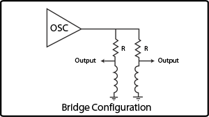
Figure 9
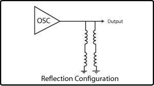
Figure 10
Bridge coils give generally good performance, particularly if the probe is designed for a specific application and frequency. Reflection coils will often give a greater gain and a wider frequency range of operation
but they are more complicated to manufacture. They also have less drift. 2
Reflection probes are also used on special probe designs that rely on the transmit-receive principle to create a certain size/shape sensitive area (like the sliding type probes).
2. TYPICAL APPLICATIONS
Surface Cracks
Normal operating frequency:
Aluminum - 100 kHz - 1 MHz
Steel - 1 MHz - 2 MHz
Inconel Titanium - 2 MHz - 5 MHz
Probes available
Pencil types - Absolute or differential . Shielded or unshielded
Surface types - Larger diameter probes can sometimes be used
Sliding probes - For cracks starting under fastener heads
Wheel probes - For bead seat radius, molded
Subsurface Cracks
Frequency must be low enough to penetrate the required depth (use slide rule or graph attached). Minimum usable frequency is 100 HZ. 3
Probes Available :
Surface probes - Normally absolute shielded. Diameter can be as large as spacing between fasteners
Encircling probes - Give better penetration. I.D. must be close to fastener head diameter
Sliding probes - For fast directional inspection (reflection)
Bore Hole Cracks
Frequency as for surface cracks
Probes available:
Absolute - (preferably shielded) in hand operated or scanner versions.
Differential - (shielded or unshielded) - hand operated and scanner versions
Probes can be expanding (contact type) or non-expanding (slightly below hole size) . Contact probes can be more sensitive to cracks (no lift - off distance) but they also generate scanning noise. Low frequency types can be used to penetrate through brass bushings. Automated systems can be implemented. 4
Coatings
Frequency varies with type of coating
Non-conductive coatings can be considered as lift-off measurements.
Metallic coatings require good penetration, but as they are normally very thin, fairly high frequencies are usable.
Standard absolute pencil and/or surface probes are suitable.
Conductivity
Using a standard absolute pencil or surface probe and a conductivity sample, it is possible to identify different alloys with a standard instrument. More accurate measurements require special
conductivity meters and probes. 5,6
Corrosion/Thickness
Frequency must be able to penetrate thickness required. Use EC slide rule or graph attached.
Best results are obtained using shielded surface probes. 7,8
3. NEW DEVELOPMENTS
Aluminum Angle Inspection
The problem was to inspect aluminum angle for cracks in the opposite side (not accesible) in one pass and with high sensitivity. In order to cover the required width, the coil has a lift-off of about .1 in. (2.5 mm).
A modified version of the sliding probe proved to be the best answer to several alternatives tried (Figure 11). A .020 in. maximum (15 mm) depth notch produced with a 1 in. diameter blade was detectable.
Lift-off variations and edge effects could be identified as such on the display.
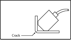
Figure 11
Thin Probe
To inspect between two lugs spaced less than .080 in. (2 mm) apart, the probe had to be shielded and be completely unsensitive at the back (Figure 12).
Using stainless steel for strength, a shielded coil was placed at the tip . A nylon handle placed at 45° allowed for better access. Such a flat coil proved very sensitive to small cracks both in steel and aluminum.
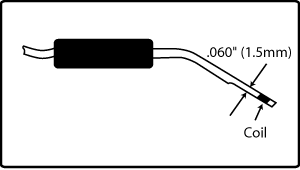
Figure 12
Small Sliding Probes
Used to inspect between fasteners in fuselage structures, a sliding probe is easier to handle than a small round probe. They give directional response with a frequency range of 1-100 kHz and penetration up to .100 in. (2.5 mm)
Sliding Probe Transparent Lens Adjustment
The sensitive area of this type of sliding probe is the distance between the driver and pick-up sections. The lens is therefore adjusted to the required width of inspection (Figure 13).
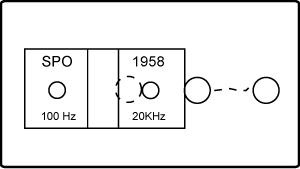
Figure 13
When scanning along a line of fasteners, this distance can also be optimized for best discrimination between the fastener indication and the defect . With no lens present, the probe is at its highest gain, but because of this it also gives a large indication for the fastener (Figure 14).

Figure 14
By allowing a thin lens, it is noticeable that the fastener indication has decreased, but the defect has not. Eventually a good compromise can be reached where the gain is not too high. The defect gives an indication that is clearly seen and the fastener only causes a comparatively small movement. A too wide lens will result in a very high gain setting and a decrease in sensitivity to short defects. 9

Figure 15
Transparent Probe Holders
When calibrating a probe in a test block with small notches, it is difficult to optimize the indication with an opaque holder. The holder is needed for stability, so
using a transparent material makes it possible to see the notch position (Figure 16) and make the calibration easier. It is also useful when scanning in confined areas or between fasteners to avoid running too close to the heads.
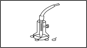
Figure 16
High Gain Probes
Sometimes standard types of EC probes are not able to give a large enough indication for the defect. This may be due to geometry, defect size or a higher than normal lift-off .
To achieve the extra gain, it is often possible to position a very small hybrid amplifier circuit within the probe body or in a separate small box close to it (Figure 17). This pre-amplifier can be tailored to a specific inspection if needed.
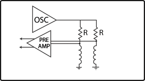
Figure 17
With this extra amplification the instrument gain can be lowered to a medium setting and the resultant signal will have a better signal-to-noise ratio than before. Care should be taken to ensure that too large of a signal does not saturate the instrument input. A quick check for this is to compare the lift- off with the edge effect. If both lines superimpose on each other, saturation is present and the gain should be lowered (there should always be a small angle separation).
A typical application has been the testing of bore holes in disks with a lift-off of up to .020 in. (probe .040 in. under size), enabling the use of a single probe size.
Extra gain has been needed to inspect aluminum-titanium sandwich structures. The titanium allows eddy currents to penetrate to the aluminum layer if the gain available is sufficient. Unfortunately, when the aluminum is covering the titanium, the eddy currents do not penetrate this as the conductivity is much lower than the aluminum, and it behaves like a shield.
If more than one probe is needed, it is possible to multiplex several probes or coils and use a single instrument. 10
REFERENCES
1. "Shielded E.C. Probes"
Process Laboratory Report
The Physical Sciences Laboratory Branch, Directorate of Maintenance,
Sacramento Air Logistics Center, McClellan A.F.B. Project No. 81-497-085,
Donald M. Bailey
2. "E. C. Development Activities"
Walter J. Harris, Boeing Commercial Airplane Co., ATA 1981
3. "Low Frequency E.C. Inspection of Aircraft Structure"
D. J. Hagemaier and A. P. Steinberg, Douglas Aircraft Company ATA 1980
4. "Update on Automated E.C. Inspection System"
Art Thompson, G.E. Evendale, ATA 1983
5. "Boeing Process Specification" , BAC 5946
6. "Evaluation of Heat Damage to Aluminum Aircraft Structures"
D. J. Hagemaier, Douglas Aircraft Company, ATA 1981
7. "A General Procedure for the Detection and Measurement of Corrosion in Aircraft Skins Using E.C.
Equipment"
J. Pellicer, Staveley NDT Technologies, Inc., NORTEC Division, ATA 1984
8. "Aircraft Corrosion and Detection Methods"
D. J. Hagemaier, A. H. Wendelbo, Jr., Douglas Aircraft Co., ATA 1984
9. "Sliding Probes with Transparent Lens", Technical Bulletin
J. Pellicer, Staveley NDT Technologies, Inc., NORTEC Division
10. "Application Advancement in E.C. Using Pre-Amplifiers and Multiplexers "
J. Pellicer, Staveley NDT Technologies, Inc., NORT EC Division,
ASNT Spring Conference, Tulsa, OK 1986