This application note explores wall thickness gauging in the blow molding industry. Learn more about the equipment, methods, calibration, and procedures used to determine the wall thickness of blow molded parts.
Quality Control of Blow Molded Parts
For many years, quality control for blow molded parts involved cutting them up with utility knives to make thickness measurement with calipers. There are several issues that arise with this conventional method of testing. When a part is cut open, a burr is usually left at the cut edge. If the operator makes a measurement over the burr, it is not a true wall measurement.
Assuming that the operator is careful and avoids distorted edges, there are still limitations as to where measurements can be made with mechanical devices. Often, the part’s geometry limits access to tight corners or handle areas on bottles. Once a part is destroyed for thickness measurements, it cannot be used for most other testing.
Variation in operator technique is another problem. Calipers can cause errors when they are held at an angle to the part. When calipers are used on materials that can be compressed by jaw pressure, thickness readings will vary from one operator to another. There is a potential safety problem as well. Operators are required to section parts with utility knives several times a shift, which introduces the risk of serious injuries.
Two electronic methods that can reduce or eliminate these challenges are ultrasonic gauging and Hall-effect gauging. Both methods are commonly used in blow molding quality control. Selecting a measuring method generally depends on the product to be tested. This application note covers key factors to consider when selecting a gauging method for blow molded parts.
How Ultrasonic Gauges Measure Wall Thickness
Ultrasonic thickness gauges provide an accurate, reliable, and repeatable way to measure wall thickness from one side of a part without damaging it. They work by measuring the time it takes for an ultrasonic sound wave to travel through the part. The transducer is placed on the surface of the part to be measured and acoustically coupled to the part using a fluid—usually glycerine, propylene glycol, or water.
Then the pulse of sound travels from the contact surface to the opposite surface and bounces back to the transducer as an echo (see Figure 1). The gauge measures the transmit time of a pulse of sound through a material (see Figure 2). Using the velocity of sound in the material being measured, the gauge calculates the thickness of the material using the following equation:
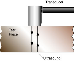

Figure 1. The transducer is placed on the part. Sound from the transducer makes a round trip between the contact surface and the back surface.
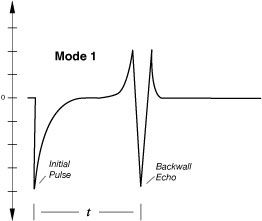
Figure 2. The initial pulse represents sound entering the part. The back wall echo represents sound returning from the opposite surface. “t” is the time of flight of the pulse of sound. Mode 1 refers to the measurement method, which used the initial pulse and the back wall echo to determine thickness.
Calibrating Ultrasonic Gauges
Ultrasonic gauges are extremely accurate if the conditions that cause errors are understood and a few simple precautions are taken. If the gauge has been properly calibrated, it will display an accurate wall thickness. The calibration process requires material samples of known thickness.
Typically, the gauge will be set up on samples representing the maximum and minimum material thickness to be measured. Material sound velocity and zero offset (a transducer-related parameter) are set by performing a simple keypad operation of entering the known thickness of reference standards. The gauge uses the known thickness to calculate a sound velocity and zero offset for that material and transducer, respectively. When the gauge makes thickness measurements, it uses the calibrated velocity to calculate the thickness of the product.
Advantages and Limitations of Ultrasonic Gauging
A primary advantage of ultrasonic gauging is that thickness measurements require access to only one side of the test material, permitting measurement of closed containers, large sheets, and other geometries where access to both sides is difficult or impossible. Gauges are generally handheld and easy to use.
A potential limitation is that the measurement accuracy is only as good as the accuracy to which the material and sound velocities are known. Consequently, this method is subject to inaccuracies if the material sound velocity changes unpredictably. Velocity can be affected by changes in the material’s properties, which include substantial temperature shifts or variations in density. Most plastics exhibit noticeable velocity shifts as the temperature changes by more than 5 °C (10 °F).
The easiest way to avoid temperature-induced errors is to calibrate and measure at ambient temperature. If that is not possible, calibration and measurement should be made at a known, constant position in the manufacturing process. As most standard transducers will be damaged by contact with parts hotter than approximately 50 °C (122 °F), testing at elevated temperatures is not recommended unless special transducers are used.
Heavy wall products—in which the inside of the part stays hot while the outer surface cools—might have large temperature variations from the outside of the part to the inside. These temperature variations can cause substantial velocity changes through the wall of the part, which can introduce measurement uncertainties.
How Hall-Effect Gauges Measure Wall Thickness
The other electronic gauging method employs a phenomenon known as the Hall effect. The Hall effect uses a magnetic field applied at right angles to a conductor carrying a current. This combination includes a voltage in another direction. A ferromagnetic target, such as a steel ball of known mass, is placed in the magnetic field, and the induced voltage is changed. As the target is moved away from the magnet, the magnetic field and the subsequent induced voltage are changed in a predictable manner. If these changes in the induced voltage are plotted, a curve can be generated that compares induced voltage to the distance of the target from the probe (see Figure 3).
To make a measurement, place a Hall probe on one side of the product to be measured and place a ferromagnetic target (usually a small steel target ball) on the other side of the product. The gauge displays the distance between the target and the probe, which is the wall thickness.
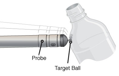
Figure 3. A target ball is placed on one side of a part to be measured. The probe is placed on the opposite of the part, and the ball is attracted to the probe.
Calibrating Hall-Effect Gauges
A Hall-effect gauge is calibrated by placing a series of shims of known thickness on the probe, placing a ball over the shims, and keying each known thickness into the instrument. The information that is keyed into the instrument during the calibration enables the gauge to build a lookup table, in effect plotting a curve of voltage changes. The gauge checks the measured values against the lookup table and displays thickness on a digital readout. While this sounds complicated, operators only need to key in known values during calibration and let the gauge do the comparison and calculation. The calibration process is automatic, so the operator does not need to know about the physics that enables the measurement.
Advantages and Limitations of Hall-Effect Gauging
Hall-effect gauging has several advantages: no couplant is used, there is no velocity variation with temperature or other material properties, and wall thickness in tightly radiused areas and in extremely thin samples can be measured. Also, it is often easy to scan the probe around the part to quickly verify thickness at multiple points or look for the minimum thickness in an area.
A potential limitation of Hall-effect gauging in blow molded plastic applications is that it is necessary to place a target ball inside the part being measured, preventing use on closed containers (which can be measured ultrasonically). The system can measure up to about 10 mm (0.400 in.) While Hall-effect gauges can measure compressible materials, the ball can compress the material. As a result, the smallest ball possible should be used when making these measurements. In production use, an operator can scan an entire part in a few seconds while storing several readings or scanning for a minimum wall. Frequently this type of unit is placed in a production area, where it is used by the molding equipment operators. This approach permits true statistical process control (SPC).
How to Select a Gauging Method for Blow Molded Parts
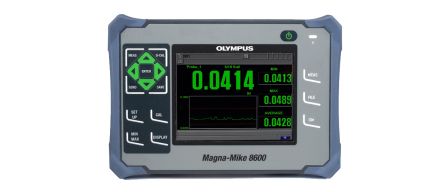
There are no hard and fast rules for choosing between the two gauging methods. In general, if measuring large, rigid parts with thick walls, the preferred method is ultrasonic. When measuring small, thin wall (less than 0.100 in. or 2.5 mm) parts with tight corners, Hall-effect gauges such as the Magna-Mike™ 8600 instrument are preferred. The majority of blow molding applications favor Hall-effect gauges. Most blow molders have parts with complex shapes, relatively thin, flexible walls, and corners that are difficult to measure with mechanical or ultrasonic gauges.
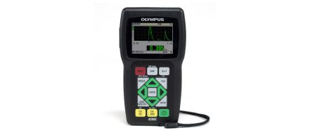
For ultrasonic measurements, a precision thickness gauge can be used. We recommend one of our standard ultrasonic thickness gauges for most common single layer plastic bottle applications. These include the 39DL PLUS™ and 45MG gauges with Single Element software. Multiple velocity and transducer setups can be stored in these gauges, making gauging of various materials a simple process. M116, M208, or V260 Sonopen™ transducers are commonly recommended for thin-walled parts. For thick-walled parts, use the same gauges with a lower frequency contact transducer, such as M112, M110, or M109. For thickness measurements on hot plastics at temperatures higher than 50 °C or 120 °F, use a high-temperature delay line transducer.
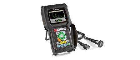
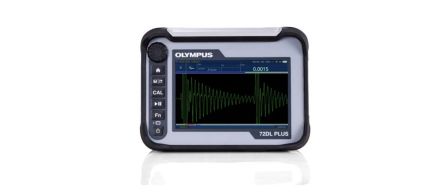
Measuring the thickness of thin plastic bottles or multilayer plastic requires a much higher frequency than is available on standard ultrasonic thickness gauges. For thin bottles under 0.004 in. (0.1 mm) and plastic multilayer containers, we recommend the 72DL PLUS™ high-frequency gauge. The 72DL PLUS gauge can use transducers with frequencies up to 125 MHz and can simultaneously display the thickness of up to six layers.
It is possible to calibrate either type of gauge quickly with a few simple steps. Once calibrated, either gauge will produce accurate, repeatable results. Users have found that operator technique is less of a factor with these methods than with mechanical gauging. Calibration data is stored with logged readings and provides a check of the operator’s work. Both the ultrasonic and Hall-effect gauges offer datalogging capabilities, helping to eliminate the risk of transcription errors.