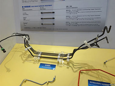
Automotive pipe assembly (Image courtesy of MarkLines Co., Ltd.)
Manufacturing Automotive Pipes
Pipes are used for various systems in an automobile, such as feeding systems for gasoline, light oil, and other fuels, as well as brake systems and intake/exhaust systems. Today, pipes are used in the feeding systems for conventional fossil fuels as well as hydrogen-powered systems. Automotive pipes are generally made of regular steel and stainless steel, as automobiles are often used in environments where iron rusts or cracks easily, such as areas with significant temperature changes or high humidity. Even worse, there is a risk that foreign matter, such as small stones, could get caught in the tire treads of a running car, hit an exposed pipe under the car body, and cause chips on the surface.
To prevent chipping, automotive pipes are coated with protective materials. Coatings used to be applied through thermal contraction, but now they are usually made with plating, paint, and resin to save on labor and costs. The coating thickness of a pipe is determined based on the purpose and location of the pipe.
The Challenges of Measuring Coating Thickness on Automotive Pipes
In the quality control process, inspectors must assess coating thicknesses to make sure they meet specifications and check for thickness variations. Coatings are applied with the minimum required thicknesses, usually in micrometers. For this reason, it is common to use microscopes to measure the thickness.
However, most pipes have outer diameters of several centimeters, making it impossible to observe them in a single field of view. To view the entire cross section of a pipe to measure the coating thickness, inspectors must stitch multiple microscope images together to create one image. The problem is, image stitching can lead to misaligned stitched images and uneven colors. Not to mention, many inspectors find it difficult to locate the section measured.

Example of an uneven stitched image
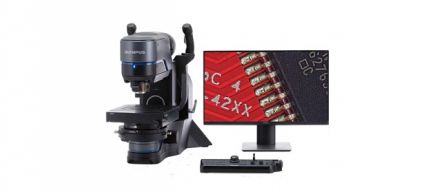
Benefits of Measuring the Coating Thicknesses of Automotive Pipes Using the DSX1000 Digital Microscope
1. Use the advanced image stitching function to create clear images of pipes.
Our DSX1000 digital microscope provides pattern matching and shading correction algorithms that enable you to stitch images together without misalignment or uneven colors. Using the microscope, you can acquire seamlessly stitched images that clearly show the cross sections of pipes.
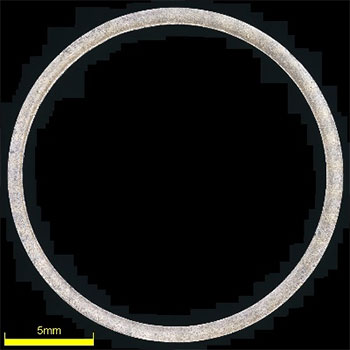
When creating a stitched image of a hollow sample like a pipe, you can quickly take images by moving the microscope stage around the pipe cross section.
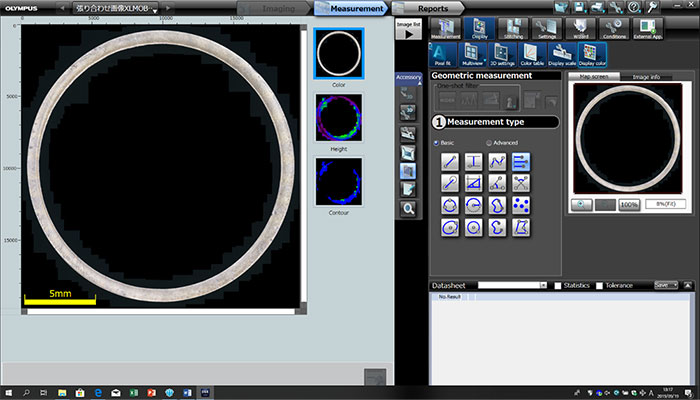
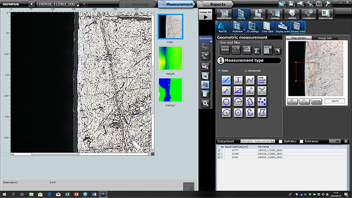
2. Measure any part of the pipe by selecting from the stitched image
You can easily select a part of the pipe from the stitched pipe image, then magnify and measure it. See how this works in the images below:
 |
 |
 |
3. Obtain reliable measurement data with guaranteed repeatability and accuracy*
Measurement data needs to be evaluated based on two factors: repeatability and accuracy. The former indicates how many similar measurements can be obtained and the latter indicates how close a measurement is to the true value. Data measured with the DSX1000 digital microscope is traceable to national standards and offers a double guarantee that it is both repeatable and accurate.
*To guarantee XY accuracy, calibration work must be undertaken by an Olympus service technician.

