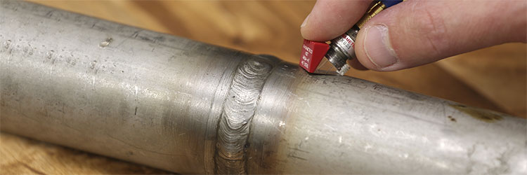
Small-diameter pipe welds can be difficult to inspect with conventional ultrasound. As the pipe diameter decreases, the area of contact between the transducer wedge and pipe also decreases, leading to less transferred sound energy. In addition, maintaining proper transducer positioning can be difficult, as rocking and improper alignment make it hard to maintain a good signal.
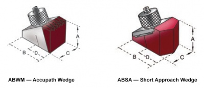
The easiest way to facilitate wedge positioning and alignment is to use a small wedge, such as our ABSA short approach wedges. The smaller the wedge footprint, the less potential for rocking and misalignment. However, wedge dimensions can be restricted by regulating codes, application geometry, and transducer size. In other cases, the part diameter is too small for even the smallest wedges. This is when contoured wedges may be necessary.
A contoured wedge or delay line is machined to match the contour of a curved part. Contouring is one way to increase the area of contact between the wedge face and the inspection piece and to help ensure the wedge is properly positioned when inspecting small diameter parts. Contouring can effectively eliminate rocking and helps to provide consistent wedge alignment.
While ABWM wedges are the most common wedges to contour, we can contour many of the angle beam wedge product lines with the exception of the ABSA line of wedges.
When is contouring necessary?
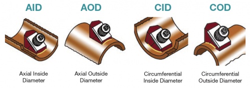
The IIW (International Institute of Welding) Handbook on the Ultrasonic Inspection of Welds recommends the use of a contoured wedge whenever the gap between the wedge and the test surface exceeds 0.5 mm (approximately 0.020 in.). Under this guideline, a contoured wedge should be used whenever the part radius is less than the square of a wedge dimension (length or width) divided by four:
R < W2/4
R = radius of test surface
W = C width of wedge if testing in axial orientation, B length of wedge if testing in circumferential orientation
Using a smaller wedge will improve coupling on curved surfaces compared to a larger wedge. As a practical matter, contouring should be considered whenever signal strength diminishes or couplant noise increases to a point where the reliability of an inspection is impaired.
Wedge options for pipe diameters < 10 in.
The following table will help you decide which wedge type to use for small-diameter part inspections. Please note that this list is only intended as a guideline. Additional factors other than part diameter may restrict wedge selection.
| Part Diameter (in.) | Orientation | Wedge Options |
| 10 | AOD | Standard ABSA, ABWM |
| 10 | COD | ABSA-4T, Contoured ABWM-5T, Contoured ABWM-7T, Contoured ABWM-4T |
| 9 | AOD | Standard ABSA, ABWM |
| 9 | COD | ABSA-4T, Contoured ABWM |
| 8 | AOD | Standard ABSA, ABWM |
| < 9–1 | COD | Contoured ABWM |
| 7 | AOD | ABSA-5T, 7T, 4T, ABWM 7T, ABWM 4T, ABWM-5T Contoured |
| 6 | AOD | ABSA-7T-, ABSA-4T, Contoured ABWM-5T, ABWM-7T, ABWM-4T |
| 5 | AOD | ABSA-7T-, ABSA-4T, Contoured ABWM-5T, Contoured ABWM-7T, ABWM-4T |
| 4 | AOD | ABSA-4T, ABWM-4T, Contoured ABWM-5T, Contoured ABWM-7T |
| 3 | AOD | ABSA-4T, ABWM-4T, Contoured ABWM-5T, Contoured ABWM-7T |
| 2–1 | AOD | Contoured ABWM |


