Gear-Tooth Surface Inspections
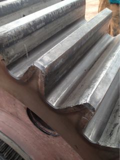 Gears are a critical component of the equipment used in the mining industry. From processing equipment to heavy equipment, all of these gears must be closely monitored for surface-breaking cracks caused by stress during operation. If these anomalies are not found during inspection, it can lead to catastrophic equipment failure.
To perform any gear inspection, the equipment must be brought to a complete standstill. To keep maintenance costs low and reduce the impact on operations, these stoppages need to be kept as short as possible in order to get the equipment back in service quickly. Gear failure while in-service is unacceptable; the costs of replacement due to such a failure are very high, mainly because of the time that the equipment is out of service. There are several types of equipment with gear components used in mining facilities, so maintaining them is a big job. Any effective gear-tooth maintenance program needs to have a reliable and efficient surface inspection method.
Maintenance managers want an overall evaluation of the gear’s condition; pinpointing any cracking is important, but the surface condition is also a major concern. Magnetic particle inspection (MPI) is currently the most common NDT method used for gear-tooth surface inspection. However, prior to performing an MPI inspection, extensive preparation is necessary. First, the gears must be cleaned of their lubricant, which is very gummy grease that is particularly difficult to remove.
Advantages of Eddy Current Array over the Standard Surface Inspection Methods:
Using eddy current array technology for gear-tooth inspection helps keep the surface preparation to a minimum, as the gears only need to be lightly cleaned. Performing an inspection with ECA is also very fast. The acquisition speed can reach up to two meters per second and only one pass is required to scan one full side of a gear tooth. The instrument calibration is very simple; all that is required is a material sample with target defect to ensure that the sensitivity is adjusted properly. Setup files can be saved and easily recalled for subsequent jobs. The data recording utility permits post-process analysis, as well as data archiving, and reports can be easily created, directly from the instrument.
- Major time savings when compared with the traditional NDT method.
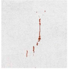
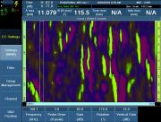
- Intuitive imaging, very similar to MPI and PT representations.
- Result traceability and post-process analysis.
- One-step inspection, high scan speed, and instant results.
- Defect depth evaluation capability.
- Adjustable sensitivity.
- Environment-friendly method (no chemicals involved).
Equipment used
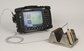
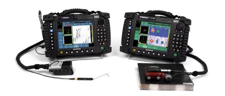
Olympus ECA solution – OmniScan MX with ECA module
- C-scan view.
- Battery operated.
- Drives up to 32 channels and up to 64 channels with an external multiplexer.
- Encoded or time-based scan.
- Data and setup recording.
Olympus ECA solution – MS5800 Instrument
- PC-based instrument.
- C-scan and 3D C-scan view.
- Drives up to 64 channels.
- Encoded or time-based scan.
- Data and setup recording.
ECA solution – Probes
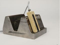
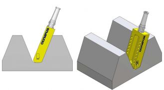
- Robust ECA probe specially designed for gear-tooth inspection.
- Transmit-receive probe design for better results.
- Absolute mode signal for easy interpretation.
- One probe covers a range of different tooth sizes.
- Two probes are usually enough to cover all tooth sizes.
- Encoder can be attached if needed.
- Customized probes can also be developed.
Replacement of Traditional NDT methods with ECA
Eddy current array can easily replace traditional NDT methods such as MPI and PT for surface inspection. ECA imaging provides similar imaging to the traditional techniques but with more possibilities. Rejection criteria can be adjusted so that it is based on probe sensitivity, a feature that is unavailable with the traditional methods.
A Variety of Familiar Color-Palette Choices Offering More Possibilities
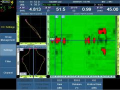
The MXE 3.0 ECA software features a range of patented color-palette representations that replicate the look of traditional NDT methods and facilitate the intuitive display of ECA signals.
Example of sensitivity adjustment that can be done using ECA method.
