Michael Moles and Sebastien Rigault
Olympus
Austenitic welds present major inspection problems due to their large grain structure. Radiography does not work well, so ultrasonics is the main choice for inspecting austenitic welds, LNG tank welds, cladding and centrifugally-cast stainless steel pipe. For ultrasonics, the large austenitic grains cause beam skewing, splitting and attenuation. This paper will review the R&D results on austenitics (including stainless steel welds, cladding, dissimilar metal welds, 9% nickel LNG welds, and centrifugally-cast stainless pipe). The R&D results, and practical experience, show that longitudinal waves are significantly less affected by the large austenitic grains than shear waves, and are generally used. However, ultrasonic inspections are further complicated by mode conversion (from longitudinal to shear waves) on reflecting surfaces, so only half skip procedures are practical. There is a hierarchy of approaches that can be used for developing inspection techniques, starting with shear waves and ending with dual matrix phased array probes. Phased array approaches are the "high end" of the inspection process, and are now competitive economically and technically. Typical techniques use phased array S-scans for multiple coverage, often with multiple passes. The actual inspection approach will depend on the material thickness, amount of weld/clad material, defects to be detected, structural requirements, rejectable defect size, time available, budget - and above all, on the grain size of the weld or cladding. The paper will give some specific recommendations on ultrasonic inspection strategies. In addition, the paper will make recommendations to improve inspectability.
Introduction
Cladding, dissimilar metal welds, austenitics all present similar ultrasonic inspection problems due to beam steering, splitting, refraction and absorption. Most of the published ultrasonic inspection work has been performed within the nuclear industry, as expected. Nuclear was the first industry to establish the source of problems from cast stainless steel pipes (specifically, large, oriented grains), and the first to model and analyze it. In general, they have shown that
- Shorter ultrasonic wavelengths but slightly larger than the grain size work best;
- Longitudinal waves penetrate better than shear waves;
- SH waves work (but EMAT devices have low signal-to-noise resolution); and
- Dual (or twin) probes are the best ways to inspect. (Dual probes pulse on one side of the array, and receive on the other to minimize near-surface reflections).
The nuclear industry has been primarily interested in cast stainless steels, which have huge grains. Experimental trials showed here that the probability of defect detection was very low. To a large extent, these results apply to Inconel and related welds (cladding, dissimilar metal welds) as the problems are the same; large, oriented austenite grains, that refract, absorb and reflect the ultrasound. Radiography suffers from similar problems to ultrasonics; the large grains cloud the image, making defect detection very difficult.
The petrochemical industry - also a large user of CRA (Corrosion Resistant Alloys) - is a different issue. There is little published on pipeline cladding and dissimilar metal welds; this is not a surprise as any information is typically considered commercial and proprietary.
The problem can be summarized as follows: ferritic materials undergo a phase transformation on cooling, which produces a quasi-random body-centered cubic structure. Austenitic welds, on the other hand, do not transform, so the austenitic microstructure is:
-γ-Fe (cubic face centered), non-magnetic
-Coarse-grain structure (up to several mm)
-Anisotropic: physical characteristics of the material (sound velocity, attenuation, beam skewing) depend on crystal orientation.
In practice, the microstructure dictates inspectability for austenitics.
Developments to Date
Nuclear: The nuclear industry has performed a significant amount of R&D on austenitic materials, including extensive modeling (1); the problem with modeling is that the microstructure can vary, so there are distinct limits to the application. The main target was centrifugally cast stainless steels (CCSS). Typical results are shown in Figure 1, though actual results will - again - depend heavily on microstructure. Cast stainless steel grains tend to be significantly larger than other austenitics, with associated inspection issues. Another problem with CCSS is that the grain size varies with cooling rate, position in the pipe, procedure etc., unlike better controlled welding processes.
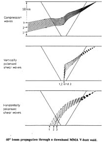
Figure 1: Sampled model beam propagation in austenitic welds for different wave modes.
The nuclear inspection techniques typically uses a low frequency L-wave transducer (or array), e.g. 1 MHz for walls up to 50 mm (2, 3), or even less. This reduces sensitivity. In the early days, longitudinal wave raster inspections were used at fixed angles, as per ASME. Conventional probes suffer from the limitations of a limited focal zone, and fixed angles. More recently, the nuclear interest in phased array S-scans has taken over, and a multiple S-scan approach is used (see Figure 2).

Figure 2: Schematic showing multiple pass scanning on weld.
More recently with the arrival of phased arrays, TRL (Transmit-Receive Longitudinal) arrays have been developed (4, 5). The TRL PA probe uses a limited matrix to provide some focusing and some lateral beam steering to adjust the focal depth. Probes typically consist of a dual array, with two rows in each side and a variable number of elements defining the length. A typical TRL PA probe might consist of 4x15 elements in two pairs of rows, as shown schematically in Figure 3.
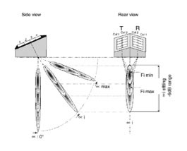
Figure 3: Schematic of TRL-PA probes, showing dual array and angled beams.
The TRL PA probes offer significant advantages over single transducers:
- First, the dead zone at the surface is minimized.
- Second, the noise level near the surface is significantly reduced.
- Third, phased arrays can perform S-scans at a variety of angles and positions.
- Fourth, the matrix TRL probe can provide variable depth focusing.
The TRL PA probe using multiple S-scans produces much better detection results than conventional UT or a single linear array (see Figure 4). The TRL PA probe also offers the best lateral sizing due to its controlled beam shaping. However, TRL-PA probes are difficult to calibrate and use, relative to linear arrays, and will be tailored to the application.
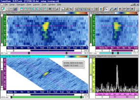
Figure 4: TRL-PA probe results on 5 mm SDH on cast stainless steel
In contrast, Time-Of-Flight Diffraction does not offer good inspection capabilities as the grain size tends to be too large for satisfactory defect detection (6).
Petrochemical Applications: These include cladding, pipelines, LNG tanks and dissimilar metal welds. By and large, these are more recent applications, and tend to use more controlled grain sizes with automated welding procedures. As such, they tend to be relatively straightforward compared with castings. Almost all the applications are "proprietary", even though the basic physics is well defined.
Figure 5 shows an example of a dissimilar metal weld inspection, using a proprietary phased array calibration technique with the reflectors through the weld material. Combined shear and longitudinal waves are used in this procedure. Reflections from the clad surface are clearly visible in Figure 5 (7).
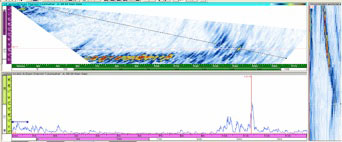
Figure 5: DSM weld inspection using phased array S-scan.
Notch above cladding is clearly visible (arrowed).
Cladding presents similar issues, as beams cannot be skipped due to mode conversion. Again, a combination of S-scans with either shear waves or longitudinal waves is recommended. Figure 6 shows a clad plate with embedded notches for reference. The notches are clearly visible with low noise level.
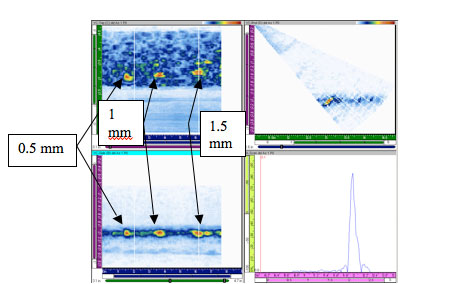
Figure 6: Clad plate with notches of 0.5, 1, and 1.5 mm depth
Being able to inspect through the weld is a major asset, though typically the weld crowns would need to be removed.
Liquid Natural Gas tanks use 9%-nickel austenitic steels for low temperature toughness. Again, the same physics applies: L-waves work better than S-waves. Figure 7 shows an example of a (patented) zone discrimination approach for LNG tanks, which is similar to pipeline approaches (8).

Figure 7: Strip chart technique for LNG tank inspection Courtesy of CB&I.
Other companies are also developing unique techniques for inspection. Applus RTD uses a similar zone discrimination approach to 7 (9). AIT uses an E-scan approach with weld overlay for positioning, as shown in Figure 8.
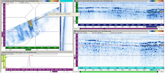
Figure 8: E-scan and A-scan (left) of lack of sidewall fusion in LNG weld. Courtesy of AIT (7).
The zone discrimination approaches tend to be more rapid, though give poorer imaging. Recent developments in more advanced systems will permit everyday inspections of pipeline welds under the usual demanding in-service conditions (10). The new PipeWIZARD v4 can drive a dual matrix array (e.g. a TRL-PA).
Superaustenitic weld inspections performed at EWI came to similar conclusions on inspectability (11).
Recommended Ultrasonic Inspection Strategy
As hopefully is clear from this paper, there are techniques available for inspecting austenitics, and they are generally known. The dominating feature is grain size; large grains present skewing, splitting and attenuation problems. In that respect, the more recent petrochemical applications tend to be a lot more inspectable than the older, nuclear CCSS pipes.
As for an inspection strategy, there is a simple approach that any capable AUT inspection company can follow.
- Try inspecting the weld with "off the shelf" conventional shear waves
- If these don't work, obtain a longitudinal wave wedge, and try that.
- Reduce the frequency from, say, 5 MHz to 2 MHz or 1 MHz (depending on thickness)
- If near surface noise is high, try a dual probe approach
- When suitable wave and frequency have been determined from conventional UT, switch to phased arrays using the same wave mode, frequency and aperture
- Develop a procedure using encoded arrays and S-scans to give full coverage at multiple angles.
- If noise levels permit, merge the data to optimize interpretation.
Note that this comprehensive approach may be unnecessary if the grain size is small. For example, Figure 9 shows phased array S-scans from a thin austenitic pipe welded using autogenous welding. The cooling rate was high, so the grains were small - and traditional shear waves were adequate for the inspection.
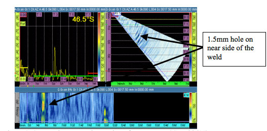
Figure 9: S-scan shear wave inspection of austenitic SS weld (11)
Possibilities for Reducing Grain Sizes
Reducing grain size is obviously the key for improved inspectability of austenitics. However, any of the techniques suggested below are likely to increase costs, and maybe increase the probability of producing defects like LOF (lack of fusion) (11).
1. Lower Heat Input: The key issues on heat input are current and travel speed. Voltage has only a minor effect. The grain size is dependent on cooling rate. The big effects on cooling rate are heat input, plate thickness, preheat. Overall, preheat is not a practical issue to control austenite grain size. It seems that heat input, and in particular, current and travel speed are the most likely parameters to control if reduced grain size is of interest.
2. Smaller Diameter Wire: Smaller wires will also provide smaller grains due to lower heat input. They should provide better fracture toughness, but will take longer to weld. If time is a critical factor, smaller wires could present a problem.
3. Change the Welding Process: Apparently some processes produce smaller grains than others. PGMAW uses pulsing to reduce heat input while still maintaining good fusion capabilities. Any of the higher intensity processes like plasma or PGMAW will be better than, say, TIG.
4. Vary the Weld Metal Composition: More ferritic metal produces smaller grain sizes. This must have implications for corrosion resistance, if not for strength. If an austenitic was chosen in the first place, it's doubtful that any ferritic will be a suitable substitute.
5. Seeding: Since grain size is really a function of nucleation and growth, seeding should offer some potential for reducing grain sizes. B (boron) has been suggested, though apparently it can lead to cracking. This is an unlikely solution.
Summary
- There does not seem to be a single "perfect" solution for austenitics, cladding and dissimilar metal welds, and there may never be one.
- The key is the microstructure of the welds; if the grains are large and oriented, there will be problems.
- The current solution is to try several techniques in a hierarchy, and chose the most appropriate technique.
References
- J.A. Ogilvy, "Ultrasonic Beam Profiles and Beam Propagation in Austenitic Weld using a Theoretical Ray Tracing Model", Ultrasonics, Vol. 24, No. 6, 1986, p. 337.
- M. Delaide, G. Maes and D. Verspeelt, "Appendix VIII qualification of manual phased array UT for piping", G Maes, J Berlanger, J Landrum and M Dennis, Insight Vol. 48, No. 4, April 2006, P. 240.
- A. Bulavinov, M. Kröning and F. Walte, "Ultrasonic Inspection of Austenitic and Dissimilar Welds", IVth Pan-American Conference on NDT, Buenos Aires October 2007.
- M. Delaide, G. Maes and D. Verspeelt, "Design and Application of Low-Frequency Twin Side-by-Side Phased Array Transducers for Improved UT Capability on Cast Stainless Steel Components", 2nd International Conference on NDE in Relation to Structural Integrity for Nuclear and Pressurized Components, New Orleans, May 2000.
- G. Selby, "Developments in the USA: Looking to the Future", 6th International Conference on NDE in Relation to Structural Integrity for Nuclear and Pressurized Components, Budapest, Hungary, October 2007.
- R. Martinez-Oña, S. Viggianiello and A. Bleuze, "On Qualification of TOFD Technique for Austenitic Stainless Steel Welds Inspection", European Conference on NDT 2006, Berlin.
- J. Halley and M. Moles, "Advances in the NDT of Dissimilar Metal Welds", Materials Evaluation, December 2008, P. 1241.
- R. Kruzic, "Ultrasonic Examination of 9% Ni Inner Shells of Liquid Natural Gas (LNG) Storage Tanks", FabTech 2008
- J. van der Ent, N. Findlay, N. Portzgen, O. Nupen, G. Endal and O. Forli, "Automatic Ultrasonic inspection of Pipeline CRA Layer", 12th Asia-Pacific Conference on NDT, 10 November 2006, Auckland, New Zealand.PWZ v4, Australia
- M. Lozev et al., "Inspection of Superaustenitic Stainless Steel Welds using Phased Array Ultrasonic Testing", EWI Project No. 446461RP, April 2003.
- S. Rigault and M. Moles, "PipeWIZARD Version 4 - A New, Improved Pipeline AUT Girth Weld Inspection System", Materials Australia, Surfer's Paradise, Australia, August 2009.
- D. Fairchild, private communication.

