Introduction
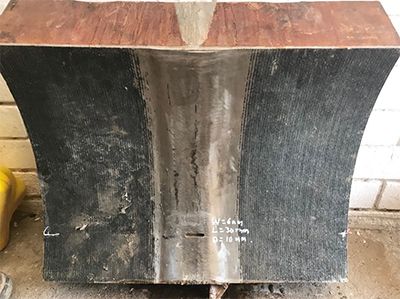
In the oil and gas, petrochemical, and power generation sectors, thick-walled components, such as pipes, are commonly used. To keep costs low, these thick components are usually made of simple carbon steel and lined with an overlay (cladding) of a more corrosion-resistant alloy (CRA) to extend the life and increase the safety of the system. These same corrosion-resistant alloys can also be used as filler for the weld, which is the case for the part shown in Figure 1. This component came from a pipeline that carried a corrosive chemical under high pressure, so carbon steel alone was insufficient to contain the flowing liquid and resist corrosion for a sustained period. When the weld material differs from the part material, this is referred to as a “dissimilar weld.” Dissimilar welds present challenges for nondestructive testing (NDT). In the past, radiography testing (RT) was often used to inspect these dissimilar materials. However, thick materials require much longer exposure times, increasing the overall RT inspection time and cost. These difficulties, as well as advances in the field of phased array technology, make ultrasound a viable alternative for these types of inspections. | Figure 1 — 95 mm (3.74 in.) thick component with dissimilar weld material and overlay |
Challenges of Inspecting Dissimilar and Thick Welds
There were two main challenges to this pipeline inspection. The dissimilar material of the weld and cladding, as well as the thickness of the component (95 mm (3.74 in.)).
Inspecting dissimilar materials with the conventional shear wave technique is difficult. When a beam travels through a component containing a weld, both the metalmetal interface and the coarse-grained structure of the weld can cause reflection (backscatter) and refraction of the ultrasonic waves. This, in turn, leads to skewing, splitting, and attenuation of the ultrasonic beam. (See the application note “Easy Ultrasonic Phased Array Inspection of Corrosion-Resistant Alloys and Dissimilar Weld Materials” for more details).
In addition to the dissimilarity issue, thick components also have their specific challenges. More energy needs to be propagated into the part to achieve good probability of detection and accurate readings.
Solution Using the A26 Dual Linear Phased Array Probe
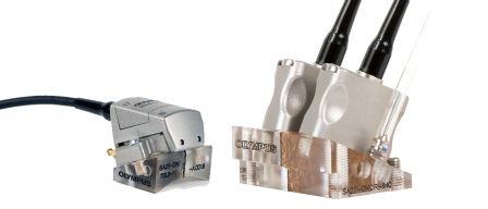
The A26 DLA probe was designed to solve the problems faced when inspecting thick dissimilar welds. This probe model uses a low-frequency, large-aperture, and TRL (transmit-receive longitudinal) technique. Since low-frequency longitudinal waves are significantly less affected by skewing and attenuation, they are a better prospect for dissimilar material inspection than shear waves. The transmit-receive or pitch-catch configuration also allows more sound (energy) to be sent into the thick component without the drawback of increasing the noise level.
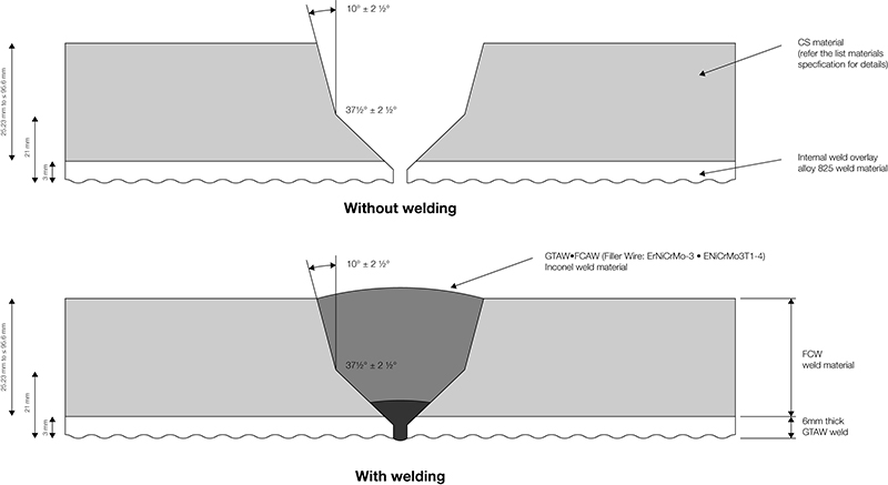
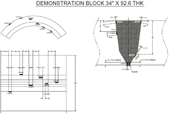
Figure 2 — Drawing of the bevel and dissimilar weld profile
Because of the mode conversion (from longitudinal to shear wave) that occurs when the wave reflects off a surface, only half skip procedures are practical (direct beams).
For this inspection, the component was 95 mm (3.74 in.) thick with a carbon-steel base material, a welded overlay of 825 alloy, and a nickel alloy (ErNiCrMo-3 + ENiCrMo3T1-4) weld filler (see Fig.1). The weld was grounded flush to enable scanning for possible transverse flaws (at 0 degrees and 180 degrees, as illustrated in the Fig. 7 scan plan).
Two different probe frequencies were used. The bottom of the demonstration block was the area of interest (shown in Fig. 4). To detect side wall lack of fusion defects, the ID notch height, and all longitudinal defect lengths, the A26 5 MHz phased array (PA) probe was used first. A lower frequency (A26 2.25 MHz) probe was then used to achieve the penetration in the more attenuative nickel alloy filler material at 0- and 180-degree skew angles (Fig. 5).
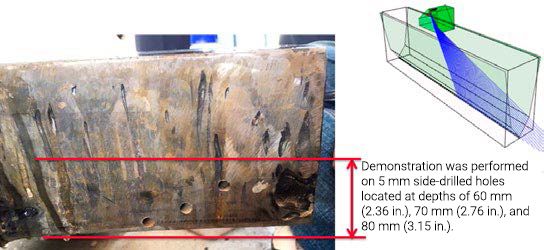
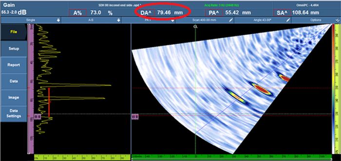
Figures 7 and 8 show the 5 mm (0.20 in.) diameter SDH (side-drilled hole) transverse defects that were measured precisely with the A26 2.25 MHz probe, even deep in the thick filler material.
Advantages of Using the A26 DLA Probe on Thick, Dissimilar Welds
We have achieved good results using our Dual Matrix Array™ (DMA) and Dual Linear Array™ (DLA) probes to solve noisy or dissimilar material applications. Some examples of this success can be found in the following application notes, “Dual Matrix Array for the Inspection of Acoustically Noisy Welds” and “Inspecting Small-Diameter, Austenitic Steel Pipes using a Dual Linear Array (DLA) Probe.” However, certain thick-walled applications still posed a challenge for previous probe models. The A26 DLA probe was designed with thick components in mind. Its lower frequency enables better penetration, and its pitch-catch configuration and larger aperture transmits more energy into the part, without increasing the noise level.
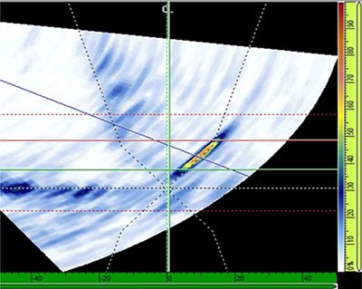
Figure 5 — Comparison of the A17 and A26 probes’ S-scan results for a longitudinal defect
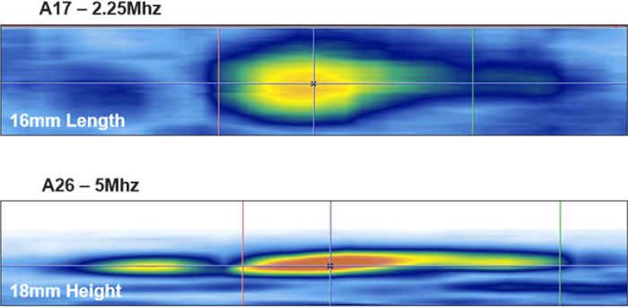
Figure 6 — Comparison of the A17 and A26 probes’ C-scan results for a longitudinal defect
Conclusion
The new A26 probe provided a better sizing performance than our other smaller dual array probes.
Because of the 5 MHz A26 PA probe’s larger aperture and higher frequency, it measured side wall lack of fusion defects, ID notch height, as well as all longitudinal defect lengths more precisely than the 2.25 MHz A17 probe.
The A26 2.25 MHz probe was capable of penetrating the Inconel® 825 (nickel alloy) filler at 0-degree and 180-degree skew angles.
Figure 7 — Demonstration block with transverse defects (5 mm (0.20 in.) diameter SDHs) at depths of 60 mm (2.36 in.), 70 mm (2.76 in.), and 80 mm (3.15 in.). Scan performed at skew 180 degrees in filling material.
Figure 8 — Sectorial scan showing 5 mm (0.20 in.) diameter SDHs at depths of 60 mm (2.36 in.), 70 mm (2.76 in.), and 80 mm (3.15 in.).
