Frequently Asked Transducer Questions
Q: What is the difference between Olympus transducers from the Panametrics-NDT and Harisonic product lines? A: These are two legacy product lines offered by Olympus, and most of these offerings have been re-branded as Olympus probes. There is significant functional overlap between them. Typically, the Harisonic probes will only be offered if there is not currently an alternative Olympus transducer available. Consult a sales representative for further details. | 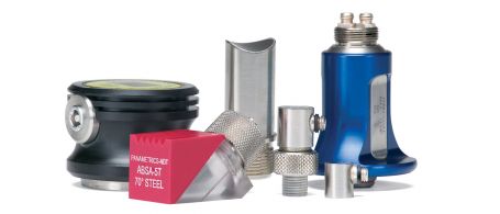 |
Q: What are the differences between the Olympus Accuscan®, Videoscan®, and Centrascan® transducer series?
A: In short, Accuscan (S) transducers are narrowband units optimized for penetration, Videoscan transducers are broadband units optimized for near-surface and axial resolution, and Centrascan transducers incorporate composite elements to combine high sensitivity with broad bandwidth. See page 4 of the conventional ultrasonic transducer catalog for further details.
Q: What is the near-field length/beam diameter/beam spread angle/etc. for my transducer?
A: Formulas for calculating all commonly used beam parameters can be found in the Technical Notes section at the end of the conventional ultrasonic transducer catalog.
Q: What is the temperature limit for standard Olympus transducers?
A: For all contact and immersion transducers, the recommended limit is approximately 50 °C (125 °F). Internal components are bonded and cured at or near room temperature and are stable at room temperature. Elevated temperatures can cause the internal components to expand at different rates. Due to the varying rates of thermal expansion, stresses can overcome the strength of internal bond lines and cause catastrophic failure. Transducers that have been thermally damaged will be dead or exhibit extreme loss of sensitivity and cannot be repaired. Customers who need to work at temperatures above 50 °C (125 °F). should use a high-temperature delay line or dual element transducers. Details of each are found in the catalog.
Q: What is the maximum excitation voltage that can be applied to Olympus transducers?
A: In spike and square wave mode, lower frequency transducers (below 10 MHz) can typically be excited at 400–475 volts, while at 10 MHz, voltage should be limited to 300 v. In tone burst and continuous wave systems, the voltage and duty cycle must be limited to prevent transducer overheating. See the technical notes in the catalog for detailed guidelines, including the formula used to calculate the maximum voltage and duty cycle in specific cases.
Q: Can Olympus calibrate my transducer?
A: Piezoelectric transducers convert electrical energy to mechanical energy and vice versa. Olympus transducers are incapable of being "calibrated" by means of adjustment. However, we can document their performance in accordance with ASTM E1065 and our manufacturing specifications. The available tests are described on page 7 of the transducer catalog.
Q: Does Olympus manufacture transducers for the medical industry?
A: Our industrial transducers are designed for use in industrial applications such as flaw detection, thickness gaging, and material properties research. We do not sell our industrial transducers for medical diagnostic applications. However, we do occasionally sell them to biomedical researchers doing a variety of interesting research work.
Q: Does Olympus offer high-power transducers for industrial cleaning, homogenization, cavitation, ultrasonic welding, etc.?
A: No. Typically these applications require power levels much higher than those used in ultrasonic nondestructive testing. By definition, NDT causes no changes in the test material, thus all transducers designed for NDT applications are low-power devices. We recommend no more than 0.125 watts of average power as an electrical input for the majority of our standard transducers. Processes like cleaning and cavitation require power levels in the tens or even hundreds of watts. That is outside the scope of our NDT business.
Q: Can Olympus transducers be used in through-air applications?
A: No, non-contact measurements are not possible through air with our standard transducers. The power levels and frequencies used in ultrasonic NDT are not optimum for sound transmission through air. Airborne ultrasound applications typically use frequencies below 50 KHz.
Q: What are the dimensions of the case? A: This information can be found in the dimensional drawings for each type of transducer in the catalog. Q: What is the wear surface material? A: The specific identity of most materials used in our transducers is considered commercially proprietary. The gray material is a carbide and the pink material is a ceramic. Both are extremely hard and wear resistant and have excellent durability as well as acoustic coupling properties. |  |
Q: What is the case material?
A: All Olympus contact transducers have cases made of corrosion-resistant 303 stainless steel.
Q: Are contact transducers available with connector configurations other that the ones listed in the catalog?
A: Transducers found in the catalog are listed with their standard connectors. Other connector configurations may be possible, however an additional charge may apply.
Q: Why use a dual element transducer for corrosion/wall thinning measurements? Why not a contact transducer? A: Dual element transducers have long been the industry standard for measuring remaining wall thickness in corrosion applications. Dual element transducers generate sound waves with one element and receive with another. These elements are angled inwards toward each other (the "roof angle"), which causes the transmit and receive beams to cross under the examination surface. This design creates a pseudo-focused effect, which increases sensitivity when examining rough and pitted back wall surfaces. | 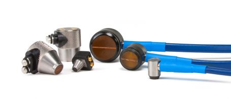 |
Q: Can these duals be used in high-temperature environments? How high?
A: Yes. Specific temperature ranges for each transducer type can be found in the relevant product pages. The highest temperature rating of approximately 500 °C (930 °F) applies to the D790 type duals. Remember that all of these temperature specifications are for brief contact, especially at the upper end, and that transducers must be used with the appropriate high-temperature couplant and allowed appropriate cooling time between measurements.
Q: What is the effective sound path depth for dual elements?
A: Many factors affect the performance of dual element transducers, including material type, backwall condition, material grain structure, type of gage or flaw detector used to drive the transducer, material thickness, part geometry, and temperature. Typical thickness ranges for corrosion gaging duals can be found on the product pages.
Q: How should one align a dual element transducer on the outside and inside diameter of a pipe?
A: The most effective way to align a dual element probe for common outside diameter (OD) inspections is to orient the center barrier perpendicular to the center axis of the tubing, as seen in the drawing below. This orientation provides the most efficient coupling.
![]()
In an inside diameter (ID) inspection, the orientation of the centerline should be rotated 90° from that position. Transducer contouring may also be required in ID tests to provide sufficient contact area.
Q: Which option is included when a delay line or protected face transducer is purchased? A: All standard replaceable delay line transducers except for spot weld transducers are shipped with a standard polystyrene delay line per the catalog illustrations. If high-temperature or dry coupling delays lines are required, they must be specifically ordered. For spot weld transducers, select a delay line of the required size from the list on the spot weld probe page. Protected face transducer part numbers do not include a delay line, membrane, or wear cap. All of those must be ordered separately. | 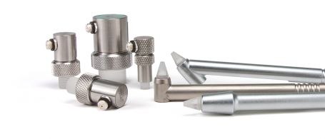 |
Q: Can the delay lines be contoured?
A: Generally yes. Check with a sales representative for geometrical limitations.
Q: Can protected face and delay line transducers be used in a high-temperature environment?
A: Yes, when used with an appropriate high-temperature delay line and couplant. See our catalog for part numbers.
Q: What is the approach distance for Olympus wedges? This refers to the distance between the beam exit point and the toe of the wedge. A: See the mechanical drawings in the catalog for specific dimensions. Q: Can you contour Olympus wedges? A: Yes, however there are maximum and minimum contour limitations for each wedge type, dependent on the angle and size of the wedge. In general, we align our outer diameter offerings with the dimensions of nominal pipe sizes. Contact a sales representative for details. | 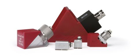 |
Q: What are the thread designations for the screw-in wedges?
A: 0.5 in. Diameter -11/16 in.-24-UNEF-2A
0.375 in. diameter—9/16 in.—24-UNEF-2A
0.25 in. diameter—3/8 in.—32-UNEF-2A
Q: Can Olympus manufacture wedges with non-standard angles for steel and other materials?
A: Yes. The customer must specify the refracted angle desired, test material velocity, and any other important factors that may play a role in the success of the inspection. Note that, in some cases, the performance will be quoted only on a "best effort" basis. A premium will apply and/or sometimes a minimum required order quantity.
Q: Does Olympus offer 35° wedges and 80° wedges?
A: Wedges at very high and very low refracted angles have significant issues with respect to Snell's Law and will generally be quoted only on a "best effort" basis. To create 35° refracted shear waves, the incident angle must be very close to the first critical angle, a "null" zone where there is no usable signal from either longitudinal or shear wave components. Very weak signals may result. There is also a high angle longitudinal component (mid 70° range) associated with 35° refracted shear wave wedges that may cause interference in some tests. At very high angles, our experience is that the highest practical refracted shear wave angle that can be achieved is approximately 75°, and wedges will be quoted accordingly. Surface wave (90°) may be an alternative in some cases.
Q: Why am I not receiving a return signal? The transducer is coupled to the test piece. A: A high-viscosity shear wave couplant such as our SWC-2 must be used to couple a shear wave into the test piece. Standard couplant will not work, because it is a liquid. A basic property of a liquid is that it does not support a shear stress. Thus, low-viscosity liquids such as conventional ultrasonic couplants will not transmit shear waves. Note also that shear wave attenuation is usually extremely high in flexible materials such as rubber and soft plastics, thus there may be no usable shear signal even with proper couplant. Hard plastics do usually transmit shear waves at ultrasonic test frequencies, but care should be taken with transducer selection and instrument setup. |  |
Q: How do I use sticky shear wave couplant?
A: For the best results, it is important to use a very thin layer, with firm coupling pressure. The suggested procedure is to put a very small amount of SWC-2 couplant on the transducer and spread it into a thin layer with a razor blade or straightedge. Then, couple onto the test piece and further wring out the couplant by rotating the transducer.
Q: What is the direction of polarization?
A: The direction of polarization of the shear wave is nominally in line with the right angle connector in standard RM (right microdot) and RB (right BNC) style cases. Shear wave transducers with SM (straight microdot) or SB (straight BNC) connectors have a line engraved on the case marking the polarization axis.
Q: I'm receiving a large longitudinal component from my normal incidence shear wave transducer. Why?
A: There are two possibilities. All normal incidence shear wave elements generate some underlying longitudinal wave energy as well. Typically, this longitudinal component is at least 30 dB lower than the shear signal; however, in materials with very high shear attenuation and lower L-wave attenuation (like flexible plastics), or in situations where non-viscous couplants are used, the shear component may be highly attenuated while some L-wave energy remains and is seen in the waveform display. A second issue is element damage caused by high excitation voltages. Shear wave transducers should be driven with the lowest excitation voltage possible, preferably 100 volts. When too much power is delivered to the transducer over time, the element can actually be re-poled to a longitudinal mode element. Higher frequencies are more susceptible to this re-poling, due to the element thickness. There is no reversing this effect, and, after re-poling, the transducer is essentially a longitudinal transducer. This effect can occur with long term use with 300–400 v pulsing.
Q: What is the difference between flat plate focus (FPF), point target focus (PTF), and optical limit focus (OLF)? A: See the technical notes section in the catalog for a detailed explanation. PTF is our default choice unless the customer requests otherwise. Q: How long can I submerge these transducers? A: For the longest service life, we recommend that our immersion transducers be time-cycled with an 8-hour submerged period followed by a 16-hour drying time. Since immersion transducers have epoxy wear surfaces or lenses, they can absorb water over time. This absorption can cause blistering on the front face, and this blistering can degrade performance and cause premature failure. Higher frequency transducers (10–20 MHz) have thinner epoxy layers and are more susceptible to damage from continuous immersion. Lower frequency probes have thicker wear surfaces, making them more robust. |  |
Q: To what depth can I submerge standard immersion transducers?
A: Generally, with standard immersion transducers and waterproof cables, the safe limit is about 9 meters (30 feet). We have had customers who purchased our standard immersion transducers and waterproof cables and modified them for underwater use for extended periods. One common approach is to coat the threaded area where water could seep in with grease or silicone and then wrap the connector area with waterproof tape. However, this is an informal suggestion, and Olympus does not warranty results.
Q: Can I use couplants other than water?
A: We warranty performance only with water couplant, the industry standard. While some customers have successfully used other fluids, the customer assumes all risk of potential damage to the epoxy lens. Note also that most alternate immersion couplants, like oil, oil emulsions, or alcohol, are significantly more attenuating than water and will affect transducer performance. They may also cause permanent damage to the lens with long-term exposure.
Q: What is the temperature limit of Olympus immersion transducers?
A: We recommend water temperatures of no more than 50 °C (125 °F). Higher temperatures can cause permanent damage.
Q: What is the maximum output power or sound pressure that can be obtained from our transducers?
A: We do not have that information available. We do not specify or measure that property because it is not a required test parameter in the ultrasonic thickness gaging and flaw detection applications that are the focus of our business. As an order of magnitude answer, the maximum recommended input power to our transducers is 125 milliwatts, and energy out is always less than energy in.