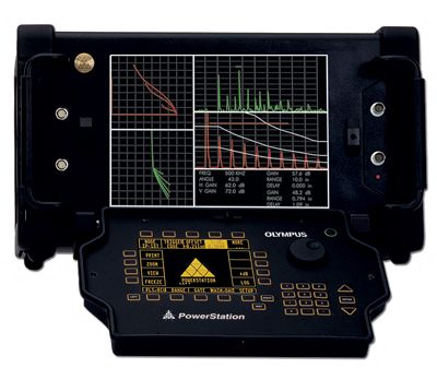
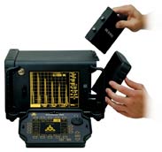
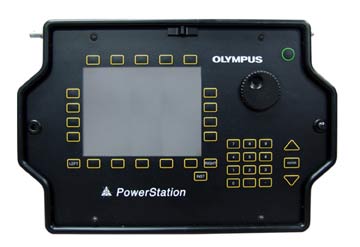
The PowerStation is a unique nondestructive testing instrument offering multiple testing methods through its innovative modular design concept. The PowerStation is capable of operating as a dedicated eddy current or ultrasonic flaw detector, or the user can choose to run both eddy current and ultrasonic tests simultaneously.
Reconfiguration of the PowerStation is achieved by simply turning the unit off, changing the module(s) and turning the instrument back on. In seconds, the instrument is ready for almost any type of inspection. And now, with PowerLinkTM technology, inspections have never been so quick and efficient. PowerLinkTM stores setup and identity information within the sensor so that the PowerStation can be rapidly configured for a specific application while documenting the exact sensor
used.
The PowerStation base unit is configured with a large 10.4" (265 mm) color LCD display with a resolution of 640 by 480 pixels. This bright screen provides high resolution and remarkable contrast to ensure accurate inspections. In addition, it can be configured for use with a VGA compatible computer monitor or projector, making it an excellent choice for classroom training or remote monitoring applications.
|
Features
|
• One to four channels of eddy current testing
• One to four channels of ultrasonic testing
• One or two channels of eddy current and/or ultrasonic testing simultaneously
• Front or rear facing module connectors
• Multiple analog, alarm, and digital outputs
• Large 10.4" (265 mm) color LCD
• USB and Ethernet communications
• PowerLinkTM Technology - automatic transducer recognition and instrument set-up
• Durable/rugged case design
• VGA output
• Windows-based WorkMaster™ software
|
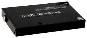
Nortec 200 Module
|
| Basic Performance | | Frequency Range: 50 Hz to 12 MHz
| | Gain: 0 to 90 dB in 0.1 steps. The horizontal and vertical gains may be adjusted together or separately.
| | Sensitivity: Adjustable to 200 volts per ohm (high probe drive).
| | Flaw Response: 0 to 2000 Hz nominal
| | Digitizing Rate: Up to 6000 samples/sec
| | Rotation: Variable from 0 to 359.9o in 1.0°, 0.5°, and 0.1° steps
| | Sweep: Variable from 0.005 to 4 seconds/division
| | Low Pass Filter: 10 - 50 Hz and wide band
| | High Pass Filter: Off, 2 to 500 Hz. 2 pole response
| | Probe Drive: 2, 6, or 12 volts peak-to-peak into 75 ohms
| | Null: 3 stage digital nulling system
|
| Display | | Variable Persistence: Screen persistence can be varied from 0.1 to 5 seconds. Timed erase cycles can be selected up to 1 minute in 1 second increments. Basic stored screen times are infinite with manual erase.
| | Screen Erase: Removes all signals from screen. Adjustable from 1 - 60 seconds
| | Continuous Null: Selectable among 0.1, 1.0, 5.0, and 10 Hz
| | Freeze: Freezes display on screen for storage or intervals.
| | Reference Memory: Allows the user to recall a stored image to compare against a live signal
| | On Screen Control: Pertinent instrument settings are displayed on-screen next to impedance display window.
| | Update Rate: 60 Hz
|
| Alarms | | Alarms: All alarms can be set to trigger on positive (signal enters alarm area) or negative (signal leaves alarm area).
| | Box Alarm: 3 separate box alarms work independently of each other.
| | Polar Alarm: Circular gate with positioning and radius adjustments
| | Sweep Alarm: High/Low threshold adjustment for use with external or auto sweep modes
| | Alarm Dwell: Selectable, 0 - 10 seconds
| | Indicator: Visual and selectable audible
| | Alarm Volume: User adjustable
| | Alarm Outputs: TTL compatible 0 - 5 volts, outputs on rear panel. Independent per alarm type features
| | Probe Types: Absolute and differential in either bridge or reflection mode. The instrument is fully compatible with Nortec PowerLink™ probes.
| | Analog Output: Rear panel BNC connectors for +/- 5 volts vertical and horizontal
|
|
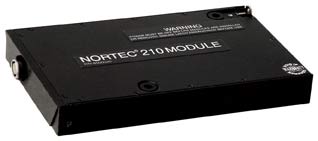
Nortec 210 Module
|
Includes all Nortec 210 Module specifications in addition to the following:
| Features | | Scanner Compatibility: Will operate the following Nortec NDT scanners: Spitfire, RA 2000, PS-5AL, RA19, PS-4, PS-3, PS-2, MiniMite
| | Waterfall Display (PS-5AL only): Stores up to 64 sweeps per hole and includes an on-screen readout of the distance from the start of the scan to the defect
| | Digital Conductivity Specification: Digital conductivity display from 0.9% to 100% IACS or 0.5 to 64 MS/m. Accuracy within +/- 0.5% IACS from 0.9% to 65% IACS and within +/- 1.0% of values over 62%. Meets or exceeds BAC 5651
| | Non-Conductive Coating Thickness: Can measure non-conductive coating thickness from 0" to 0.015" (0 to 0.38 mm). Accuracy of +/- 0.001" (0.025 mm) over 0.00 to 0.015" (0 to 0.38 mm) range
| | Conductivity Alarm: Independent High/Low limit alarms can be set for conductive values. Alarms can be triggered positively or negatively.
| Liftoff Alarm: Independent High/Low limit alarms can be set for liftoff values. Alarms can be triggered positively or negatively.
|
|
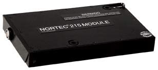
Nortec 215 Module
|
Includes all Nortec 210 Module specifications in addition to the following:
Test Modes
1) Single frequency with one probes
2) Dual frequency with one probe
Display: Frequency 1 (F1) only, Frequency 2 (F2) only, sum of F1 and F2, difference between F1 and F2, split screen with selected combinatins of F1 and F2, and mixed frequencies
Display Modes: Impedance plane, Auto Sweep, External Sweep, Waterfall, Conductivity/Liftoff
Second Frequency: 50 Hz to 3 MHz, 2nd frequency is an exact division of the first frequency in ratios of 1/2, (F1 < 6 MHz), 1/4, and even divisors to 1/32
|
Nortec 220 Module
|
Includes all Nortec 215 Module specifications in addition to the following:
Test Modes
1) Single frequency with two separate probes (2 channel). The probes are operated independently at the same or related frequencies. Either probe can be absolute or differential, bridge or reflection.
2) Dual frequency with one probe
3) Scanner compatibility through channel 1
|
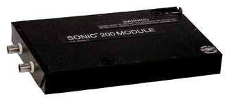
Sonic 200 Module
|
| Pulser | | Type: Square wave
| | Pulse Width: 15 to 1000 ns
| | Pulse Voltage: Selectable 50 - 300 volts, 50 volt steps
| | Damping: 20, 50, 100 or 200 ohms
| | Repetition Rate: 30 Hz to 100 Hz, 10 Hz steps. 100 Hz to 10 KHz in 50 Hz steps. Automatically limited with range, delay, pulse width and damping settings to prevent sweep wraparound and to limit pulser average power
|
| Receiver | | Frequency Bandwidth: 0.3 to 25 MHz
| | Tuning: 0.5, 1, 2.25, 3.5, 5, 10, 15, 20 MHz, High pass and Wide band
| | Gain Control: 0 to 110 dB, steps of 0.2, 1, 2, 6, and 12 dB
| | Accuracy: AWS D1.1-88, Section 6.22.2
| | +dB Switch: Selectable 6, 12, 18, 20, or 24 dB increments
| | Linear Reject: 0 to 80% full screen
| | Vertical Linearity: +/- 2% of FSH, 10% to 90% full screen per ASTM E317, Section 5.3.3
| | Modes: RF, halfwave+, halfwave-, fullwave, full wave filtered, halfwave filtered, and halfwave+ filtered
|
| Gates | | Functions: Dual IP/IF synchronized gates. Gate 1 time of flight, amplitude detection and flaw alarm. Gate 2 amplitude detection, flaw alarm and time of flight for echo-to-echo mode. IP (Initial Pulse) or IF (Interface Synchronization), operator selectable
| | Position: -1.28 to 400 inches (-32.512 mm to 10.16 m) of steel
| | Width: 0.001 to 400 inches (0.0254 mm to 10.16 m) of steel
| | Level Control: Variable in 0.5% increments, 5 to 100% of full screen
| | IF (Interface) Hold-Off: Variable to 100 inches (2.54 m)
| | Alarm Logic: Selectable, positive or negative occurrence. Gates are monitored off screen
| | Indicator: Visual or selectable audio
| | Alarm Dwell: Selectable, 0 - 5 seconds in 0.5 second increments
| | Alarm Filter: Selectable, 1 - 15 consecutive indications before valid alarm
| | Output: TTL 0 - 5 volt output at rear panel BNC and "D" connector. Updated at pulser repetition rate. Software selectable reset prior to next repetition or continuous
| | RF Gates: Dual differential for both gates 1 and 2
| | RF Gate Logic: Positive logic requires a signal cycle of either polarity cross a gate level. Negative logic requires that no signal crosses a gate level.
| | Peak Amplitude: Peak amplitude of gated signal, displayed in % screen height
| | Peak Detector: Gate 1 and 2 analog output at rear panel BNC and "D" connector correspondence with 0 - 100% displayed signal during gated period, updated at pulser repetition rate. Scale control 100 mV to 10 V with offset control +/- 1500 mV. Reset mode selection resets the output 10 s prior to the next gated period.
|
| Time base | | Range: 0.048" to 400" (1.219 mm to 10.16 m) of steel
| | Delay: -1.28" to 400" (-32.512 mm to 10.16 m) of steel
| | Velocity: 0.025 to 0.6000 in/μs
| | Horizontal Linearity: +/- 0.5% of full screen
| | Trigger Modes: IP (Initial Pulse) sweep, starts after selected delay. IF (Interface) sweep, starts after first selected interface signal. Delay control acts as hold-off control to select the desired interface signal. External, fires the pulser after receiving external trigger signal. External + IF, fires pulser after receiving external trigger signal. Sweep starts after selected interface signal.
|
| Thickness | | Range: 0.012 to 400 inches (0.3048 mm to 10.16 m) of steel
| | Resolution: To 0.0002" (0.00508 mm) at 1" (25.4 mm), 0.02% of full scale, all other ranges
| | Accuracy: +/- 0.001 " (0.0254 mm) at 1" (25.4 mm), +/- 0.2% of full scale, all other ranges
| | Video: Thickness measurements can be performed on either detected video or RF.
| | Modes: IP-1st or Echo-Echo. Auto or manual calibration
| | Trigger Modes: Edge or peak
| | Display: Sound path, surface distance and depth from surface
| | Angle: 0 - 90° in 0.1° increments
| | Diameter: 0.25 to 100 inches (6.35 mm to 2.54 m), flat (off) manual calibration
| | Data Logger: Up to 5000 measurement readings can be stored in up to 100 user defined sequential or grid blocks with alphanumeric labels that can later be recalled for review on command. Stored readings can be sent to a printer or downloaded to a computer with appropriate software.
| | Distance Output: Analog thickness output at rear panel BNC and "D" connector correspondence with 0 - 100% of selected thickness range: 1, 5, 25, 100, 400 inches (25.4 mm, 127 mm, 635 mm, 2.54 m, 10.16 m) of steel. Scale control 100 mV to 10 V with offset control +/- 1500 mV. Updated at pulser repetition rate held continuous up to the next gated period. Reset mode selection resets the output 10 μs prior to the next repetition.
| Thickness Alarm: Adjustable high/low thickness alarms
Indicator: Visual or selectable audio
| | TTL: 0 - 5 V output at rear panel BNC and "D" connector. Updated at pulser repetition rate. Software selectable, reset prior to next repetition or continuous
|
| Display | | Screen Freeze: On command, freeze currently displayed signal
| | Waveform Recall: Select a stored waveform from memory
| | Peak Hold: Display peak amplitude waveform with active signals under peak waveform. Both images can be stored together.
| | Zoom: Zoom to area under Gate 1
| | View: Allows the operator to view an expanded display with the initial display indicated by screen markers. The View key enables the operator to view the pulses before and after the initial pulse, water path, or interface.
| | Update Rate: 60 Hz
|
|
Sonic 210 Module
|
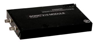
Includes all Sonic 200 Module specifications in addition to the following:
| Features | |
Back Echo Attenuation: Up to 40 dB of attenuation applied to signals under Gate 2. Selectable in 0.2 dB steps
| |
Reference Memory: Recalled waveform is displayed simultaneously with active signal. Recall waveform position is separate from active signal.
|
| DAC | | Type: Segmented with 25 operator selected points
| | Gain: 40 dB, total of gain and DAC limited to 110 dB max
| | Range: 400 μs from initial pulse
| | Slew Rate: 6 dB/μs
| | Sync: IP (Initial Pulse) or IF (Interface Synchronization)
| | Display: Selection of multiple curves showing compensation. Single curve at signal level (0 dB), three curves at +6 dB, 0 and -6 dB levels, four curves at +6 dB, 0 dB, -6 dB, and -14 dB levels, DAC compensated echoes only, single curve with DAC compensated echoes
|
|
Sonic 230 Module
|
The Sonic 230 is a two channel ultrasonic module dedicated for the PowerStation. Each channel has the same specifications as a Sonic 210 Module.
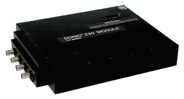
All modules are customer-interchangeable.
 |
Nortec Ps-4 Controller
|
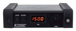
| Speed Range: Up to 1500 RPM
| | Probe Holder: 0.5 inch (12.7 mm) collet
| | Outputs: 16-pin LEMO Eddy Current signal interface. Index pulse BNC
| | Scanner Connector: 22-pin Burndy connector contains the power, signal, and interfaces.
| | Power Supply: 100 to 240 volts, 50 - 60 Hz, 2.2 amps max
| | Size: 9.25" W x 7.5" D x 3.4" H (235 mm x 190 mm x 86 mm)
| | Weight: 4.5 lbs. (2.04 kg)
| | Control: RPM is adjusted via the SmartKnob™ located on the front panel of PS-4 Controller module.
| Mounting: Controller mounts to the top of the WorkStation via 4-pin latches.
|
|
Powerstation Keypad*
|
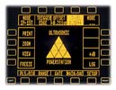
The PowerStation's universal keypad features an easy-to-read Hi-Brite electroluminescent display, which is designed to adapt to either ultrasonic or eddy current testing. The keypad attaches securely while internally integrating the cable connector for complete enclosure. An optional extension cord that allows for remote operation up to 12 feet away is available for the instrument keypad.
|
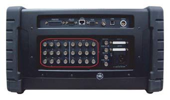
Powerstation Outputs*
|
The PowerStation comes equipped with a wide variety of standard analog and digital outputs. In addition, outputs can be customized through an expansion adapter. Most outputs are located on easy access BNC connectors. Non-standard and custom outputs are found on the standard 25-pin "D" connectors. Other outputs include: a printer port, RS-232, LAN/Modem, VGA, ACC, USB, 12 volt DC, 2 Trig In, and 2 Sync Out.
|
BNC Connector #
|
Eddy Current Signal
|
Ultrasonic Signal
| |
1
|
Vertical Mix
|
Gate 1 Analog
| |
2
|
Horizontal Mix
|
Gate 2 Analog
| |
3
|
Vertical F2
|
Detected Video
| |
4
|
Horizontal F2
|
RF
| |
5
|
Sweep Alarm
|
Gate 1 Alarm
| |
6
|
Alarm Box 2
|
Thickness Analog
| |
7
|
Vertical F1
|
n/c
| |
8
|
Horizontal F1
|
n/c
| |
9
|
Alarm Box 3
|
Alarm 5
| |
10
|
Polar Alarm
|
Gate 2 Alarm
| |
11
|
Alarm Box 1
|
Thickness Alarm
| |
12
|
Alarm 6
|
Alarm 6
|
|