Phased Array UT Data Acquisition and Analysis Software for Aerospace
AeroView™ software enables you to acquire and analyze phased array and ultrasonic testing (PAUT) data of inspections performed at 0 degrees with an overlap. This software is specially designed to facilitate the analysis of aviation and aerospace inspection data, for both manufacturing and maintenance applications. It provides you with optimized layout and readings management and advanced analysis tools to ease interpretation of the acquired data and help ensure compliance with the specifications.
Streamline Your Workflow with AeroView™ Inspection
With an AeroView Inspection software license, you can acquire PAUT data directly on a PC via an OmniScan X4 unit, eliminating the need to transfer your data. To increase productivity, AeroView Inspection gives you the flexibility to analyze an inspected part while scanning a new one, as two instances can be open on one computer.

The OmniScan X4 device runs as a black box (using the OmniScan Black Box app), and the inspection is performed on the AeroView Inspection computer. You can create your setup using ScanPlan software, adapting your layouts and palettes. Calibrate your system on a test block, and you’re ready to start. All your data is stored on your PC.
AeroView Inspection is compatible with all Omniscan X4 models and Quickscan iX PA+ acquisition units.
AeroView Software Ecosystem
AeroView Analysis software is compatible with the .nde data format. You can use it to analyze PAUT data acquired at zero degrees (with overlap) using the following instruments and inspection software:
- OmniScan X3 series (all models)
- OmniScan X4 flaw detectors (all models)
- AeroView Inspection software, when driving an OmniScan X4 unit
In-Depth Analysis of Indications for Reliable Verdicts
Leverage the software’s analysis tools to improve your indication characterization capabilities.
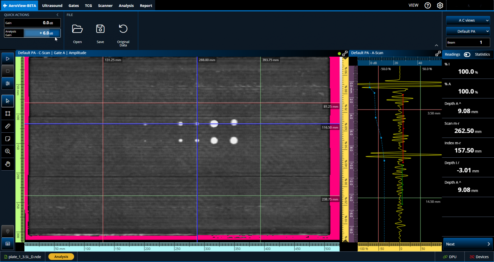
Add Gain During Analysis
The Analysis Gain setting enables you to add or remove gain for to fine-tune the data during your analysis.
Soft TCG Toggle
Soft TCG enables you to add and remove additional TCG points during your data analysis. You can easily toggle this software gain on and off.
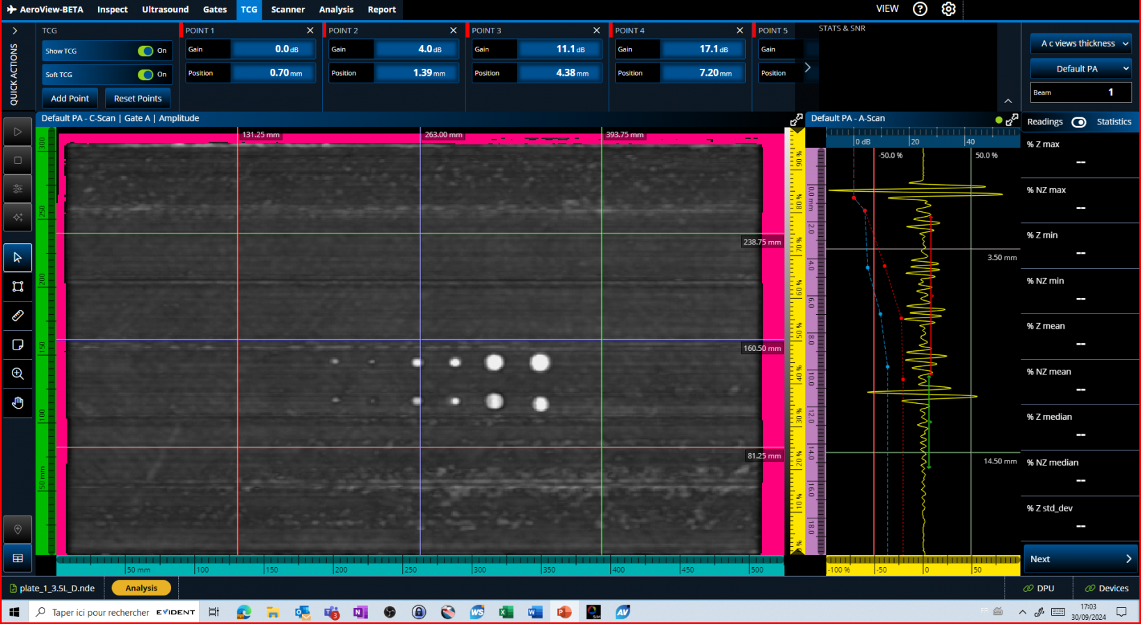
Here we see the TCG that was applied during data acquisition (the blue dots and dotted line).

Now we see the C-scan image with the TCG soft for analysis toggled on (red dots and dotted line) and the user adjusted the gain by clicking and dragging the TCG points.
Examine Your Data in Detail
Enlarge a data view so it fills the screen or zoom your C-scan to one-to-one ratio to see every aspect of each indication and improve your characterization.
Full-Screen Mode | 1:1 Ratio View |
 Normal viewing mode. |  C-scan when viewed using the standard ratio. |
 Full-screen mode toggled on for the C-scan. |  1:1 Ratio viewing activated. |
Compile All Indications in a Table for Your Report
Create an indication table that is customized according to the parameters you need, such as flaw type, readings, threshold, and verdict. The indication table data is stored along with a snapshot image of each indication for your report.
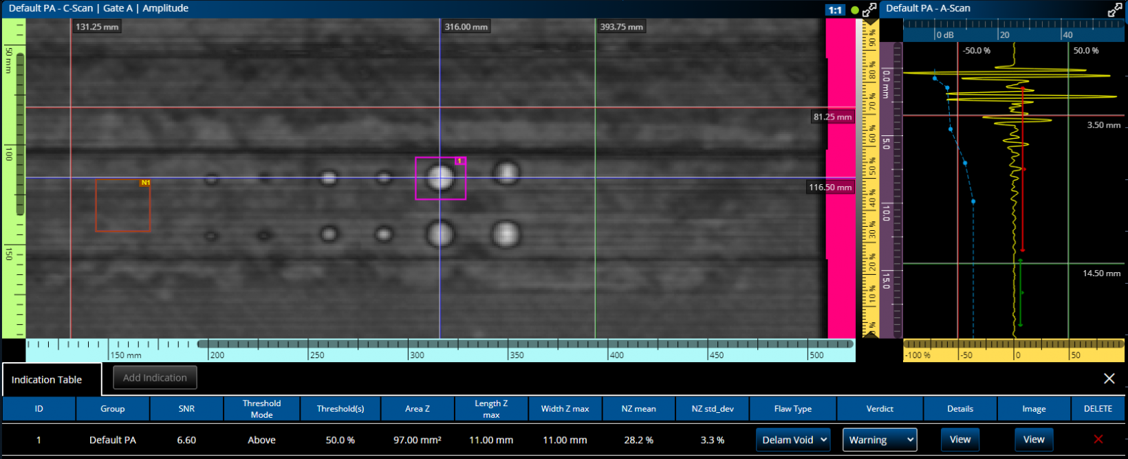
Signal-to-Noise-Ratio (SNR) Calculation
Increase the productivity of your 0-degree PAUT inspections while meeting signal-to-ratio calculation requirements of aircraft manufacturers.
The SNR calculation tools include:
Noise Zone (NZ) | SNR Calculation (Defect Zone) |
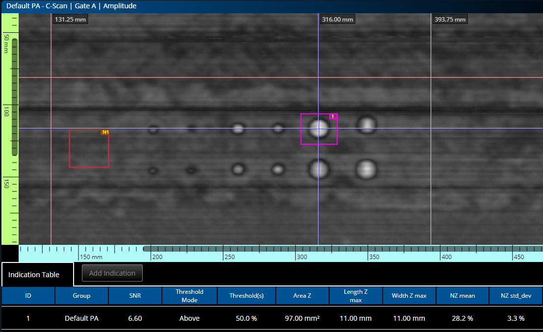 Right-click to create a noise zone (brown box) where the standard deviation of pixels vs amplitude is computed. | 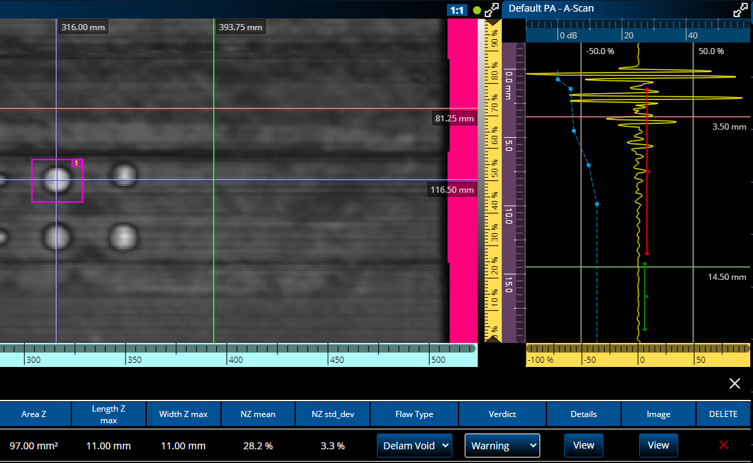 Left-click to draw the pink box around a defect to automatically calculate the number of pixels below the established threshold. |
Automatic Contrast
After the threshold has been correctly set for a flaw in a reference standard, you can toggle on the automatic contrast to easily identify indications that exceed the limit.
 |  |


