Executive Summary
Emerging optical metrology techniques offer a host of advantages for industry, and developing standards for traceable calibration of optical instruments is a vital step towards the widespread application of technologies such as confocal laser scanning microscopy.
Metrology experts at the Physikalisch-Technische Bundesanstalt (PTB) at Braunschweig, Germany, discuss their latest work in developing areal calibration standards (including multi-step height, microform and areal roughness standards) for 3D imaging techniques such as optical and atomic force microscopy (AFM). As part of this project, the Olympus LEXT OLS4000 confocal laser scanning microscope was used as a workhorse, investigating designed and fabricated standards and their applications, comparing the designed nominal value to the real ones. This presents a first step in bringing these standards into the official domain – calibrating an optical instrument for comparable and traceable results, or verifying its properties to achieve input for the estimation of the uncertainty budget.
Introduction
Characterizing the property of surfaces is a central task throughout industry, and it is vital that quantitative results are comparable to others globally. This is enabled through traceable instruments calibrated with high-quality standards, which are formulated and realized by national metrology institutes such as the Germany’s Physikalisch-Technische Bundesanstalt (PTB) independently or in collaboration with others (see Box 1).
Surfaces play an important role in modern technologies due to their functional behavior toward the environment or their contact with other surfaces. In modern fabrication processes the established technique of stylus profilometry is not sufficient to provide the necessary data or parameters to describe properties such as self-cleaning surfaces, low friction surfaces or cylinder head surfaces in car engines. Here a two-dimensional or 3D measurement technique, such as 3D confocal laser scanning microscopy (CLSM), is mandatory. Such modern instruments can achieve the necessary lateral as well as height resolution through a short wavelength, appropriate optics and a high level of pixel data, quickly and without touching the surface. However, to achieve high precision and stable values it has to be ensured that the data is comparable worldwide over long time periods. For this, standards represent a defined set of parameters, and although there are many well-established standards available for traditional methods such as the stylus, for the latest optical techniques these are not yet fully comprehensive. Currently, for optical instruments only 2D or profile-based surface roughness standards are used, and the situation is still open for areal standards.
In response to this, the PTB is therefore working to establish robust and easy-to-use areal standards for the calibration, verification or validation of the main optical areal surface measurement technologies. These are vital in order for industry to utilize the many benefits of new optical inspection techniques such as 3D confocal laser scanning microscopy (CLSM), which offers improved resolution, speed and efficiency. In developing these new standards, the PTB chose the Olympus LEXT OLS4000 as a benchmarking tool, driving the next generation of industrial metrology techniques.
Exploring this work in more detail, Dr Ludger Koenders, Dr Rolf Krϋger-Sehm, Dipl.–Ing André Felgner and Dipl. Phys. Thorsten Dziomba from the PTB spoke with Olympus’ Product Manager and Application Specialist for materials science microscopy, Markus Fabich.
The Guardians of the Unit- The Physikalisch-Technische Bundesanstalt
The PTB performs many tasks concerning the determination of fundamental and natural constants, including:
The realization, maintenance and dissemination of the SI units
- Services and metrology in areas regulated by law and industry
- Safety engineering
- Providing the time for Germany with two cesium atomic clocks
- Researching on optical laser clocks to reduce uncertainty
Dr Ludger Koenders leads the Surface Metrology department, which is divided into five working groups. Dipl.-Ing Felgner and Dr Krϋger-Sehm (retired in 2012) are part of the 3D Roughness Metrology working group, who develop and improve measuring devices, measuring procedures and calibration standards used in the field of surface metrology as well as the development of guidelines. Dipl. Phys. Thorsten Dziomba is a member of the scanning probe metrology working group.
These standards (material measures) can test a range of parameters (Figure 1), traceable to the SI unit of length. Dr Koenders comments: “All products need this traceability to function properly, to ensure all goods produced in Germany are comparable to others in both definition and specifications.”
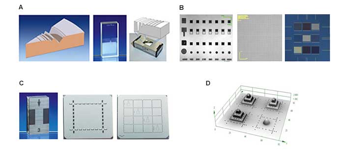 |
Figure 1: Types of calibration standards (examples).
|
Areal standards under the spotlight
In order to develop novel high-quality standards, the PTB pushes beyond the limits of optical metrology techniques, working far beyond the manufacturer’s specifications of each instrument to gain new knowledge. With this approach, the main components contributing to the measurement results and its uncertainty can be specified or estimated in a better way. As Mr Felgner says, the aim of the PTB is to reach the limit of instruments in determining the level of uncertainty, while typical industrial applications require a more pragmatic situation with more relaxed levels of tolerance: “We always have to look closer at the system, understanding how it works and why.” Many aspects of measuring areal parameters using optical metrology have been explored using the Olympus LEXT, including multi-step height, microform, chirped grating, areal roughness, lateral resolution and lateral distortion in the field of view.
Areal roughness: A comparison with AFM
Evaluating surface roughness over an area is a common task throughout industry. Supporting the widespread use of optical metrology for this task, it is important to look at how an optical technique such as CLSM compares to other approaches. Therefore optical measurements are compared alongside measurements from the atomic force microscope (AFM) instrument at the PTB. This AFM presents a reliable and accurately calibrated system against which to compare the measured data of CLSM using the Olympus LEXT.
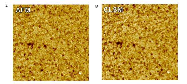
The main areal roughness parameters were analyzed on a new set of developed silicon-based roughness standards [1] including Sa (mean height), Sq (root mean squared height) and Sz (maximum height of the surface). Filters (λs, λc) were not applied, in order to directly compare both sets of data, and only a tilt correction of first order has been applied. The data are shown in Figure 2, where an excellent agreement can be observed between the Olympus LEXT and AFM roughness measurements on samples under development. The Sa value is slightly higher for CLSM, but the basis for this difference is not yet fully understood in terms of vertical axis calibration and image artefacts. The plots showing the “x-average fourier” (Figure 2C) is analog to the power spectral density of the instrument. This indicates that the LEXT and the AFM agree over a long range of spatial wavelength, with the exception of a small range at the right end, i.e. at a small spatial wavelength, where the AFM has an advantage in resolution.
 |
 |
| Figure 2: Surface roughness characterization - a comparison of CLSM and AFM. This experiment used a silicon roughness standard with marked reference fields. After lateral alignment, the two images and data were compared. The Olympus LEXT image (B) very closely agrees with the AFM image (A). C) AFM and LEXT agree over most spatial frequencies (>500 nm, i.e. 2 µm-1), and the AFM detects finer details than the LEXT only at smaller spatial wavelengths. |
Multi-step height determination
The usual calibration of the vertical axis of 3D microscopes employs a single step height standard of appropriate height. In addition to this, the use of multiple step heights can help to determine deviations along the vertical or z-axis, which is vital for accurate measurements of structures covering a larger range of height values – like microform or very rough surfaces.
The standard for multi-step height has been designed and produced both in a microscopic and macroscopic version by the PTB (Figure 3), and exhibits an arrangement of several steps depending on the magnification objective to calibrate. Mr Felgner adds: “You can also use a single step height standard, of course, by placing it in the center of the field of view and lifting it several times by different gauge blocks. However this is time-consuming and is not so accurate.”
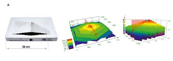 |
| Figure 3: PTB’s novel standards for multiple step height determination. A) The macroscopic multiple step height standard includes a variety of height steps for large range instruments. |
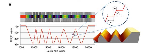 |
| B) The microscopic standard provides several defined step heights for typical microscopic instruments, enabling fast and precise linearity investigations along the vertical instrument axis in the measurement volume. |
Lateral resolution
For high quality surface metrology it is an aim to resolve the finest structures on surfaces. A high lateral resolution is therefore necessary, and this is especially important in accurate and precise manufacturing tasks. Optical lateral resolution is often determined based on the ability to detect contrast between black and white regions of a sample grid, and using this technique the lateral intensity resolution of the LEXT is found to be 0.23 µm.
However, lateral resolution in surface topography needs to be understood in another way: as the property to transfer the position-height data in an appropriate way without large distortions, i.e. the better the agreement of measured to real profile, the higher the fidelity of the instrument. Based on this latter approach, the standard developed by the PTB tests the “profile fidelity” by measuring multiple gratings with different spacing or wavelength. While each groove has a constant amplitude of 0.4 µm, these vary in wavelength, forming a chirp with a range of wavelengths from 91 µm to 10 µm and from 12 µm to 3.7 µm in two sections of the area. Figure 4 shows how, as the wavelength decreases, the ability to measure the amplitude accurately is impaired. Hence, when we reach the limit of the instrument’s profile fidelity, it is no longer able to measure height accurately. The exact definition of profile fidelity is still under discussion, and can be determined by three separate means: where accuracy remains at 100%, where the measured amplitude drops to 50%, or where a height feature can be observed but not measured.
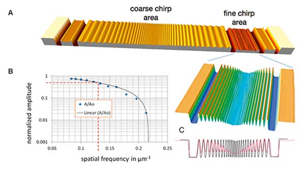 |
| Figure 4: Testing the limit of profile/structure fidelity. A) The standard has a constant amplitude (Ao) of 400 nm and a scale of 24 wavelengths from 91-10 µm in the coarse chirp area and 12-3.7 µm in the fine chirp area. B) Interference microscope with a 10x Mirau objective shows collapse of structure fidelity towards smaller structure elements, with a lateral resolution of 7.3 µm using the 50% criteria (red dashed line). In contrast, at 10x magnification the LEXT provides much better results. With 50x or 100x magnification it can even resolve the structure of the finest gratings completely and measure the height correctly. C) Mean profile measured by a stylus profilometer (black) shows only a slight decrease of measured amplitude for the finest grating, while the above-mentioned interference microscope (red) collapses. |
Lateral distortion in the field of view
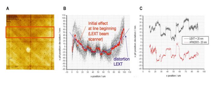
Evaluating the lateral distortion of optical imaging systems is also important for accuracy, since unlike the uniformity of a CCD grid, for example, errors can arise from non-linearity. “Compared to the well-characterized AFM system, we want to know what happens with the scale system of the CLSM sensor,” says Mr Felgner. To compare lateral distortion in the field of view, a standard formed from a 2D grid with a pitch of 300 nm in both lateral directions (i.e. 3333 periods per mm) was visualized with both CLSM using the Olympus LEXT, and AFM (Figure 5). Detected positions and even values of stitching errors of the electron beam lithography (EBL) writer used to produce these standards agree fairly well for both measurement techniques, indicating a highly accurate linear scale in the CLSM sensor.
Good Practice Guidelines
Supporting industry in ensuring reliable use of optical metrology within different industrial applications, it is an important component of these standards to define good practice guidelines for optical instruments, including confocal microscopes. If a user wants to examine a certain surface, it is vital to know which instrument to use and the exact configuration of this, in addition to the expected level of uncertainty.
Within the OptAssyst project (www.optassyst.de) a software-based system has been developed together with partners in assisting three-dimensional areal measurements of technical surfaces using optical instruments. This enables the reliable use of optical microscopes within industry. Dr Krϋger-Sehm explains: “While the manufacturer has a set of desired specifications of the surface, the operator within the metrology laboratory has the knowledge to say how this can be measured. This knowledge must be brought together – specifications of the surface and knowledge about instruments – and this is the role of OptAssyst.” The system guides the operator through a menu to find the right parameters of optical systems for the measurement task, including choosing the appropriate instrument and optics, and standards necessary for calibration. The software then guides the user through different instrument calibration steps, providing the result of the uncertainty calculation for the measurement task owing to the actual instrument behavior. The Olympus LEXT is being used as a representative confocal laser scanning microscope by the PTB to determine the quality of features on surface topography standards.
The future of optical metrology
At the PTB, the Olympus LEXT has been instrumental in bringing optical metrology into the official domain, facilitating the development of areal metrology standards and, for example, benchmarking surface roughness analysis against a well-established AFM. Working towards the integration of optical metrology within industry, the system has played a central role in investigating new standards.
“It is essential that standards adapt to new techniques, and industry needs a larger variety of standards for optical instruments,” says Dr Koenders. The LEXT provides a fast and powerful means to research and characterize new standards, enabling users to accurately interpret measurement results. The development of reference standards in this way is a vital step towards enabling industrial workflows to benefit from the many advantages afforded through optical metrology.
References
[1] Frühauf, J., Krüger-Sehm, R., Felgner, A., Dziomba, T., “Areal roughness standards”, Proc. 12th International Conference of EUSPEN, Vol. 1: pp. 133 - 136 (2012)
*1 The shown examples are for the convenience of readers and do not constitute an endorsement by Olympus or PTB, nor are they necessarily the best products available for the purpose in question.
*2 The newer second generation shows neither stitching errors nor any other significant grating inhomogeneity.
