Overview

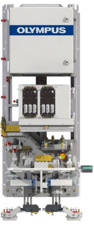
ERW Off-Line systems use phased array (PA) technology to inspect weld seams and the heat-affected zone (HAZ) of electrical resistance welded (ERW) tubes used in the oil and gas industry for oil country tubular goods (OCTG) and line pipe. Two PA probes, one positioned on each side of the weld, provide complete coverage of the weld and HAZ at a constant amplitude.
Strict Quality Control of the Weld and HAZ on the ERW Pipe Production Line
High-quality Olympus PA probes are integrated into our fully automated ERW Off-Line testing systems to meet the stringent requirements for weld inspection as well as international standards governing pipe manufacturing. The automated systems can be installed anywhere in the manufacturing process, and the flexible configuration options offer manufacturers solutions that are suited to their needs. The system inspects the internal and external surfaces of the weld seam in ERW pipes, ranging from 60.3 mm to 660.4 mm OD, in addition to the heat-affected zone (HAZ). The following typical defects are detected in the weld using the dedicated weld inspection system:
- Longitudinal cracks
- Through-drilled holes (TDHs)
- Lamination defects in the HAZ (up to 25 mm on each side of the weld)
Key Features of the ERW Off-Line Automated Turnkey Solution
- Complete coverage of the weld and HAZ provided by phased array probes scanning at a constant amplitude
- Automatic weld tracking and live probe positioning (for certain configurations)
- Automatic probe positioning centers with the weld line prior to inspection
- Dependence on operator skill is minimized
- Easy and fast changeover using preset probe holders and saved setup files
- Weld inspection can be combined with full body inspection to meet all needs with one system
Configuration Options
Several system configurations are available to achieve ERW off-line inspection according to your needs and specifications.
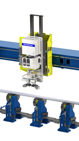
Gantry-Guided Dedicated Weld Inspection
The dedicated weld inspection system can be mounted on a gantry system, enabling the inspection of pipe cut to length in a designated area. The gantry approach provides greater control of the untested ends, minimizing the lengths. Water wedges are mounted on a servomotor-driven axis for precise positioning, automatic calibration, automatic probe positioning, and automatic weld tracking (for certain configurations).
Combined Weld and Full Body Inspection
The dedicated weld and full body ERW-OL system combines both inspections on the same gantry.
Two configurations are possible: the weld and full body inspection on opposite sides of the gantry for maximum productivity or combined on one side to reduce the footprint compared to the two-sided configuration.
Several modes are possible to suit the inspection requirements, including full body inspection using all modes (longitudinal, transverse, lamination, and wall thickness measurement) and lamination detection mode only for the pipe-end inspection of line pipes. The dedicated weld inspection is always performed with the most stringent control.
When combined with full body inspection, options such as automatic weld positioning and weld deviation tracking can be included to optimize the inspection time and provide traceability.
Dedicated Weld Inspection—Conveyor Feeding System
A pass-through configuration can be used to inspect cut-to-length ERW pipes. Using the same mechanical platform and probes as our ERW In-Line system (for infinite length pipe), this ERW Off-Line system can be installed on a feeding conveyor. A special automation sequence coupled with sensors and encoder wheels will inspect pipes quickly with a high level of reliability and repeatability.
The weld tracking signal automatically drives the flaw detection probes to help ensure optimal positioning during inspection and to record the weld position for traceability.
When weld lines have limited shift and automatic tracking is not required, a lower cost option uses a fixed weld profiling probe and alarm to warn the operator when the acquisition strays from the region of interest. Even without a servomotor-driven axis, the PA probes provide complete coverage of the weld and HAZ at a constant amplitude.

Phased array ERW-OL system used for cut-to-length pipe
Automated Calibration
The automatic calibration bench serves 2 purposes:
- Enable the operator to calibrate the system quickly and efficiently without interruption.
- Perform the calibration-in and calibration-out sequence at line speed without having to call back the reference pipe on the conveyor line.
Software and Acquisition Unit
Phased Array Acquisition Unit
The QuickScan™ PA 32:256 module meets IP55 standards and is designed to easily integrate into industrial environments.

Easy Setup
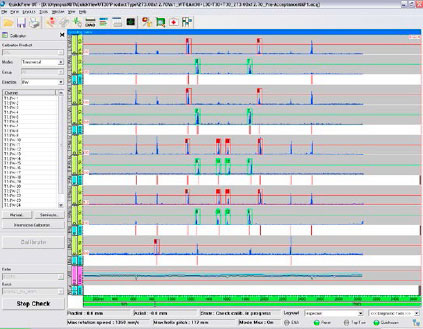
QuickView™ software makes it easy to set up the system and acquire and manage data.
The software’s wizard makes it simple to create setups for each part size. The inspection configuration and calibration parameters for each bar diameter are saved and easily retrievable. The final results are merged and displayed to clearly differentiate between accepted and rejected tubes.
- Quickly access predefined inspection setups
- Restrict access to certain users to help minimize operator errors
- Calibration and inspection information are stored for traceability
- System can be integrated within your inspection application, facilitating an operating mode that requires minimal human intervention
Specifications
System Performance
| Standard Product Range | Diameter | 60.3 mm to 660.4 mm (2.375 in. to 26 in.) (larger diameters possible for certain configurations) |
|---|---|---|
| Standard Product Range | Wall Thickness | 3 mm to 16 mm (0.118 in. to 0 630 in.) (thicker wall measurements also possible upon request) |
| Standard Product Range | Speed | From 600 mm/sec to 1500 mm/sec according to the system configuration and product size |
| Standard Product Range | Coverage | According to system configuration, the following coverage can apply:
|
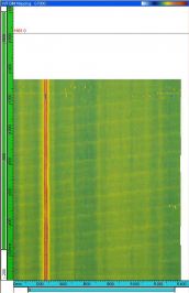
| Data Presentation | Real-Time Inspection Results | C-scan, A-scan, B-scan, strip charts, and alarms |
| Inspection Modes | Typical Inspection Modes | Longitudinal, transversal, lamination, and wall thickness measurement |
| Pipe Temperature | Up to 60 °C (140 °F) | |
| Detection Capabilities for Typical Reference Defects | Repeatability | Longitudinal notches: <2 dB Transversal notches (full body inspection only: <3 dB 3.2 mm TDH: <3 dB 1.6 mm TDH: <4 dB 6.35 mm flat-bottom hole (FBH): <3 dB 3.2 mm FBH: <4 dB 1.6 mm FBH: <5 dB 0.8 mm FBH: <5 dB |
| Detection Capabilities for Typical Reference Defects | Standards | ISO, API |
| Reporting and Data Storage | Report Types | Inspection, calibration, and calibration-check user-configurable reports |
| Reporting and Data Storage | Storage | Real-time database inspection data storage |
