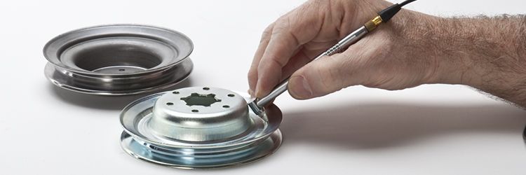
Thickness gaging ultrasonic transducers come in all shapes and sizes and choosing the right one is an essential first step in any inspection. Choosing the correct transducer depends on a few factors, including the thickness, material, and geometry of the part you want to measure. The V260 Sonopen® transducer is a popular option for many challenging thickness gaging applications because of its unique shape.
What’s the Sonopen?
The V260 Sonopen is a 15 MHz, 0.125 in. (3.175 mm) element diameter transducer with a distinctive pencil-style case. It has a focused delay line with a narrow tip and a focal depth of 0.012 in. (0.30 mm) in steel and 0.025 in. (0.64 mm) in plastic. One of the Sonopen transducer’s most important features is its narrow delay line tip—a 2 mm diameter tip comes standard, and a 1.5 mm diameter tip version is available.
The narrow delay tip enables the Sonopen to couple to very small radiuses and concave surfaces where standard delay line transducers would not be able to pick up a signal, and the pencil case enables you to access hard-to-reach places. In fact, these transducers were originally designed to measure the corner thickness of blow-molded plastic bottles, which are usually about 0.20 in. (0.51 mm) thick with a concave radius.
Common Applications
- Reduction rate testing
- Small wires and insulating jackets
- Radiused materials and tubes with a minimum radius of ~0.1 in. (2.5 mm)
- Braze joint testing
- Concave surfaces
- Aircraft skin blending
While the Sonopen works well for some applications, we don’t recommend it for general use. The narrow delay tip makes it difficult to keep the transducer properly aligned with the surface of the inspection material, and misalignment can lead to decreased signal amplitude or a loss of signal altogether. However, if your application benefits from using a Sonopen, here are 3 tips to help you achieve a consistent signal.
3 Tips to Improve Your Results
Use an instrument with an RF waveform display
When using a Sonopen, even a slight misalignment can negatively affect your results. Using an instrument with an RF waveform display gives you the information you need to be sure that you’re picking up the correct back wall signal.
Instruments with an RF display include the 38DL PLUS® and 45MG (with activation of the 45MG-WF software option) thickness gages and the EPOCH® 650 and EPOCH 6LT flaw detectors.

An RF waveform display.Customize your Sonopen to fit the application
Make sure you choose the correct Sonopen configuration for your application. Pick and choose what you need from the options below to customize.
Case Style
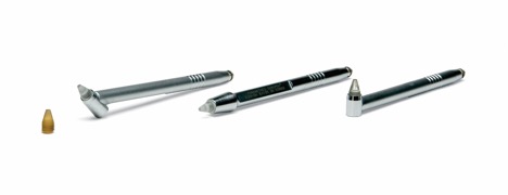
There are 3 Sonopen cases with different tip orientations—straight (V260-SM, most frequently used and recommended), at a 45-degree angle (V260-45), and at a 90-degree angle (V260-RM).
The Sonopen comes in three case styles—45° (left), straight (center), and 90° (right).Delay Lines
The Sonopen supports a variety of replaceable delay lines with different tip sizes and materials. The standard delay tip (DLP-3) has a 0.08 in. (2 mm) tip diameter and is included with the V260 Sonopen. The DLP-302 has a smaller, 0.060 in. (1.5 mm) tip diameter, and the DLP-301 high-temperature delay line has a 0.08 in. (2 mm) tip diameter and is rated for use on materials up to 350 °F (175 °C).For materials that have similar acoustic properties to the standard DLP-3 delay line, the DLP-301 can be used instead to improve performance. The high-temperature material of the DLP-301 can provide a greater impedance mismatch between the delay tip and test material, yielding a larger interface echo. This makes it easier to observe and take a measurement from the interface echo between the materials.
Holder and V Notch
The optional spring-loaded holder (SLH-V260-SM*) helps to maintain alignment with the test piece, and the V notch is especially useful when measuring small-diameter tubing.*SLH-V260-SM is only compatible with V260-SM
Make sure there’s couplant under the delay line
Sonopen transducers do not have permanent delay lines. Like all replaceable delay line transducers, they require couplant between the delay line and the face of the transducer to transmit sound. Without couplant, no sound will be transmitted to the delay line. Over time, couplant can dry out, resulting in decreased signal amplitude. We recommend that you check for couplant under the delay line before each inspection and apply more as needed.
Related Content
Wall Thickness Gaging in the Blow Molding Industry
Void Detection in Molded Plastic Parts
Wall Thickness of Turbine Blades
Thickness Measurements on Rubber Hoses and Tubing
Get In Touch

