Evident LogoOlympus Logo
Recursos
Notas de aplicação
Voltar para Recursos

Aircraft Composite Inspection with 35RDC Ramp Damage Checker


Application

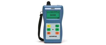
Solid laminate aircraft composites can be internally damaged by impacts in a way that is not visible on the outer surface. The Model 35RDC Ramp Damage Checker is a simple hand-held ultrasonic instrument designed for preliminary screening of aircraft composites to identify areas of possible subsurface impact damage. It is normally used with a 5 MHz broadband contact transducer, part number V109-RB. The range of composite thickness that can be tested is 0.025 in. to 0.900 in. (0.635 mm to 22.8 mm).

CAUTION

  • The Model 35RDC is intended for preliminary screening only. It is not intended to replace comprehensive testing by a trained operator using an ultrasonic flaw detector.
  • When using the 35RDC, users are responsible for making sure they have been trained for any particular inspection and are following the recommended inspection procedures outline in the Service or repair manual provided by the component or aircraft manufacturer.

Theory of operation

Ultrasonic sound waves travel through materials in a predictable way. When a high frequency sound pulse generated by an ultrasonic transducer is coupled into a piece of solid laminate composite, it will travel through the material until it encounters an air boundary, at which point it will reflect back as an echo that can be detected by a gage. In the case of structurally solid composite, that reflection will come from the backwall or the inside surface of the laminate. If, however, there is a delamination or subsurface cracking parallel to the surface, then the reflection will come instead from the damaged area and arrive earlier in time. The difference in the echo patterns from good versus damaged material can be used to identify areas of internal damage that are not visible from the surface.

The default alarm setting for the Model 35RDC will respond to delaminations occurring in the composite material within a nominal 2 ply thickness buffer zone from the back wall, to accommodate for velocity variations, slight thickness variations or ply drops.

Procedure

The Model 35RDC gage is not intended to scan large areas. Rather, it is used to screen areas of suspected damage.

The 35RDC gage must first be calibrated for the specific thickness of material that is to be tested. The user normally identifies an area that shows impact damage and then moves to a point three to six inches (75 to 150 mm) away from this spot to an area that appears to be clean. The ultrasonic transducer is coupled to this known good area of the material and the operator presses a calibration key. The gage identifies the backwall echo from the far side of the composite at the calibration point and establishes it as a reference. The gage then switches into test mode and the user may move the transducer to the suspect area.

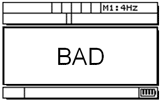
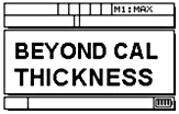
When the transducer is coupled to a test point, the gage compares the new echo pattern to the reference pattern. If an echo is received earlier than the backwall echo, or if the backwall echo is not present, that indicates probable damage and the gage displays the indication BAD. If an echo is received earlier than the Calibrated backwall echo window, or if the backwall echo is not present, that indicates probable damage and the gage displays the indication BAD. If only a strong backwall echo is received within the calibration window, then the gage displays the indication GOOD. If only a strong backwall echo is received but it is beyond the calibration window, then the gage displays the indication as "BEYOND CAL THICKNESS"

Because this analysis is based on the reference echo, the 35RDC must always be recalibrated whenever switching to an area of different thickness or different material. This calibration procedure normally takes only a few seconds. If an attempt is made to measure material of a different thickness without recalibration, the gage will display either BAD or BEYOND CAL THICKNESS depending on whether the new material is thinner or thicker than that used for calibration.

IMPORTANT NOTE: Any "bad" indication should be investigated further by a trained NDT professional who is familiar with composite inspection. Testing with the Model 35RDC gage is for preliminary screening only and is not equivalent to comprehensive testing by a trained inspector.

Example:

1. Solid laminate - echo from back wall is detected

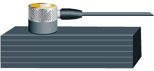
good screentransducer testing sampletest results screen

The ultrasonic pulse reflects from the far side of the laminate, creating a echo at a specific point in time. The gage used this echo as a reference.

2. Delaminations - echo from fractures is detected

bad screentransducer testing bad samplebad test results

The ultrasonic pulse reflects from the fracture, creating a echo that arrives earlier than the calibration point. The gage identifies this as a delamination.

3. Material is beyond calibrated thickness - echo occurs outside measurement window

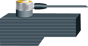
byeond calibrated thickness screentransducer testing large samplebeyond thickness screen

If the material thickness changes, the pulse from the back wall is shifted in time. If the new material is thicker than the calibration standard, the gage identifies this as a "beyond calibration thickness" condition.

Olympus IMS

ProductsUsedApplications

O verificador de danos de compósitos 35RDC é um medidor ultrassônico passa/não passa simples projetado para detectar defeitos em subsuperfícies causados por danos de impacto em estruturas de compósitos de aeronaves.

Desculpe, esta página não está disponível no seu país
Diga-nos o que você está procurando preenchendo o formulário abaixo.
Desculpe, esta página não está disponível no seu país