Executive Summary
The Harvard School of Engineering and Applied Sciences required a measurement tool for quantifying the relationship between a natural insect wing, a micro-machined silicon mold and a fabricated wing.
The School of Engineering and Applied Sciences (SEAS) serves as the connector and integrator of Harvard's teaching and research efforts in engineering, applied sciences, and technology while fostering relationships with industry and government labs or serving as an "incubator" for new ventures.
Within SEAS sits the laboratory of award winning Professor Robert Wood whose research focuses on all aspects of mobile micro robot design, fabrication, control, and analysis. His lab's expertise in micro fabrication and micro system design combined with insights from nature has enabled the creation of high-performance micro robots for aerial and terrestrial environments. Such systems can be used for search and rescue, hazardous environment exploration, environmental exploration, monitoring and reconnaissance.
The Olympus OLS4000 Laser Confocal System at Professor Wood's lab is used to provide accurate morphological measurements in the creation of micromolds and fabricated insect wings.
Re-creating Nature
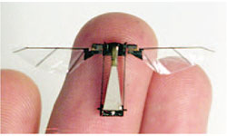 | With the right tools and staff, Professor Robert Wood and Dr. Hiroto Tanaka were confident they could re-create the wing of a hoverfly. And they did! Their team was able to produce an artificial insect wing made of polymer and hinged with carbon fibers within a time span of approximately one year. Since insect wings are responsible for flight mobilization, characterization of wing structure in 3-dimensions is vital. A wing's 3-D structure significantly affects the wing flexibility and the resultant aerodynamic performance during the insect's flight. |
Attention to detail during fabrication, especially profile measurements, was of utmost importance. The LEXT OLS4000 Laser Scanning Confocal Microscope from Olympus was chosen over a SEM and stylus profilometer as the preferred optical metrology tool for this project. The reason for this was the SEM is not able to measure height and a stylus profilometer lacks the ability to measure critical wall-like steep profiles as the stylus tip (typically having a square pyramid shape) will collide with the side wall and never reach the bottom. A feature of the OLS4000 is the ability to quickly and accurately measure deep cavities and 85 degree sloped walls.
 Real Wing Fabricated Wing |
Quantifying the Process Method
After formal design of a hoverfly wing it is necessary to create a mold that will serve as the basis for manufacture. Painstaking efforts are taken to duplicate the intricate topographical features from both the top and bottom of the wing into a silicon mold.
Silicon is chosen for mold material due to its favorable compatibility with laser ablation etching properties. Laser ablation is used numerous times to etch/replicate the exact details. With 10 μ thin membranes, 50-125 μ vein heights and 100 μ corrugation heights one can imagine this is not an easy task.¹ The OLS4000 was used to integrate these three different micro-scale features as a quick check during the ablation process. After each ablation, the OLS4000 was used to provide feedback on etch depths, with an acceptable variation of ±0.3 micron/step. A scan with the OLS4000 took less than 1 minute-a very fast process with results deciding whether further ablation was necessary or not. Resulting measurements of the surface profiles of the natural wings, the molds, and the newly fabricated wings were able to demonstrate the high accuracy of this new replication molding process method.
Measuring Square Shaped Channels
As mentioned earlier the topology of fabricated wings also needs to match their natural counterparts. Aside from structure, wing profile also may play a role in various flight performance characteristics. An insect's wing profile affects the magnitude of aerodynamic lift and drag. Most importantly, the wing profile determines the wing flexibility and resultant deformation during flapping flight.
The LEXT OLS4000 utilizes dual confocal pinholes and detectors that increase the system's sensitivity such that sidewalls of up to 85 degrees can be imaged and measured. Because Dr. Tanaka's mold designs required deep-etch U-shaped channels with high aspect ratios, the OLS4000 was the only laser scanning confocal system that was able to accurately measure these critical surface features.
In addition, the stitching capability of the OLS4000 was key in making measurements and following structural features across a wider field of view. Stitching is a software technique that allows a number of high resolution images to be combined into one. This provided one cohesive profile measurement to be taken on what was now the entire wing section.
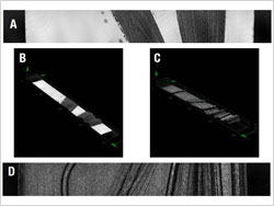 A. Fabricated wing, smooth side, 2-D B. Fabricated wing, smooth side, 3-D C. Fabricated wing, vein side, 3-D D. Fabricated wing, vein side, 2-D |  Cabon Hinge Overview. OLS4000 Brightfield CCD non-confocal mode, Objective lens MPLFLN 2.5X |
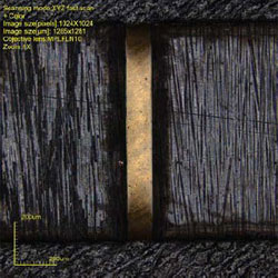 Carbon Hinge. OLS 4000 Laser confocal mode with color overlay. | 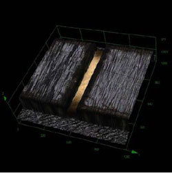 Carbon Hinge. OLS 4000 Laser confocal mode, 3D. |
Verifying Carbon Hinge Quality
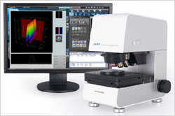 Olympus LEXT OLS4000 Laser Scanning Confocal Microscope | At the base of the artificial wing is a hinge that consists of two components-rigid carbon fiber parts that are black and an extremely narrow film flexure that is white. Of particular significance is the resultant thickness and width after laser ablation. Width fidelity is extremely critical as this affects the overall stiffness of the hinge. This was accomplished utilizing the OLS4000's brightfield CCD non-confocal imaging mode in conjunction with the calibrated ruler feature. In addition, a scanned laser image was used to obtain and verify the thickness which was 80 microns ±5 microns. |

